Ga naar Gerards page / go to Gerards other pages ---->>> ![]()

Akai aa5810 refurbishment / recap / modifications 
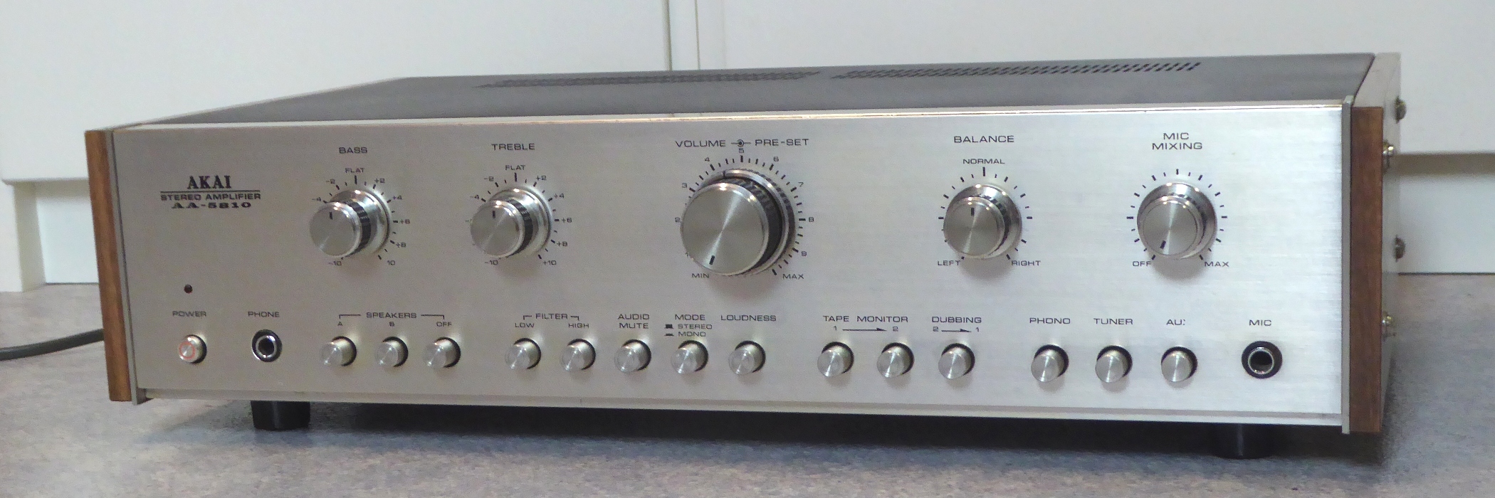

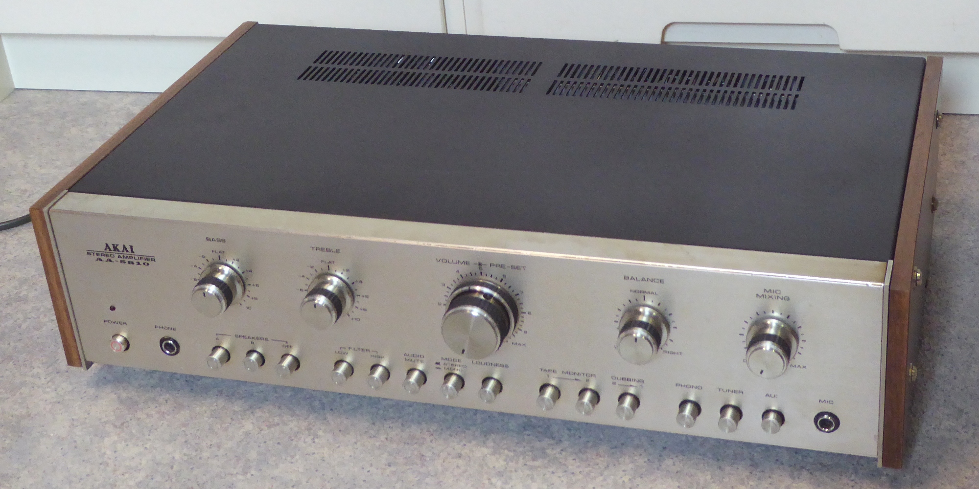


This Akai was sold during 2024, paying for a 55 years old Sugden A21 and the parts to refurbish it ;-) .

![]() Gemakshalve is deze pagina alleen in het Engels geschreven.
Gemakshalve is deze pagina alleen in het Engels geschreven.
![]() This page is written using English language only.
This page is written using English language only.

Its power section was seriously burnt, and a blackened spot was in the power supply section too.
As a whole the amp was in a bad shape, so I decided just go ahead and refurb without paying attention to the reason of any defects encountered, as just about all parts would be replaced anyway.
All electrolytic capacitors and resistors were replaced throughout the amplifier, several film capacitors and most transistors also, a VBE multiplier modification was done for the main amplifier bias settings.
Enjoy the picture showcase.


The pre-amplifier part of the amplifier

The pre-amplifier consists of an equalizer/switch board, a volume/mike mixer board, and a tone controls board.
As the pictures show, taking this all apart, it is a real mess of wiring.

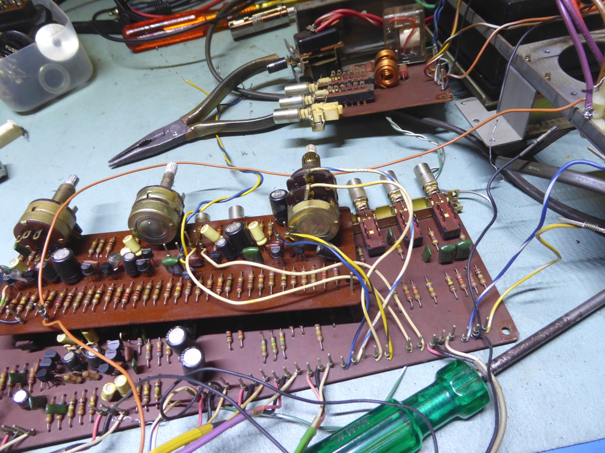


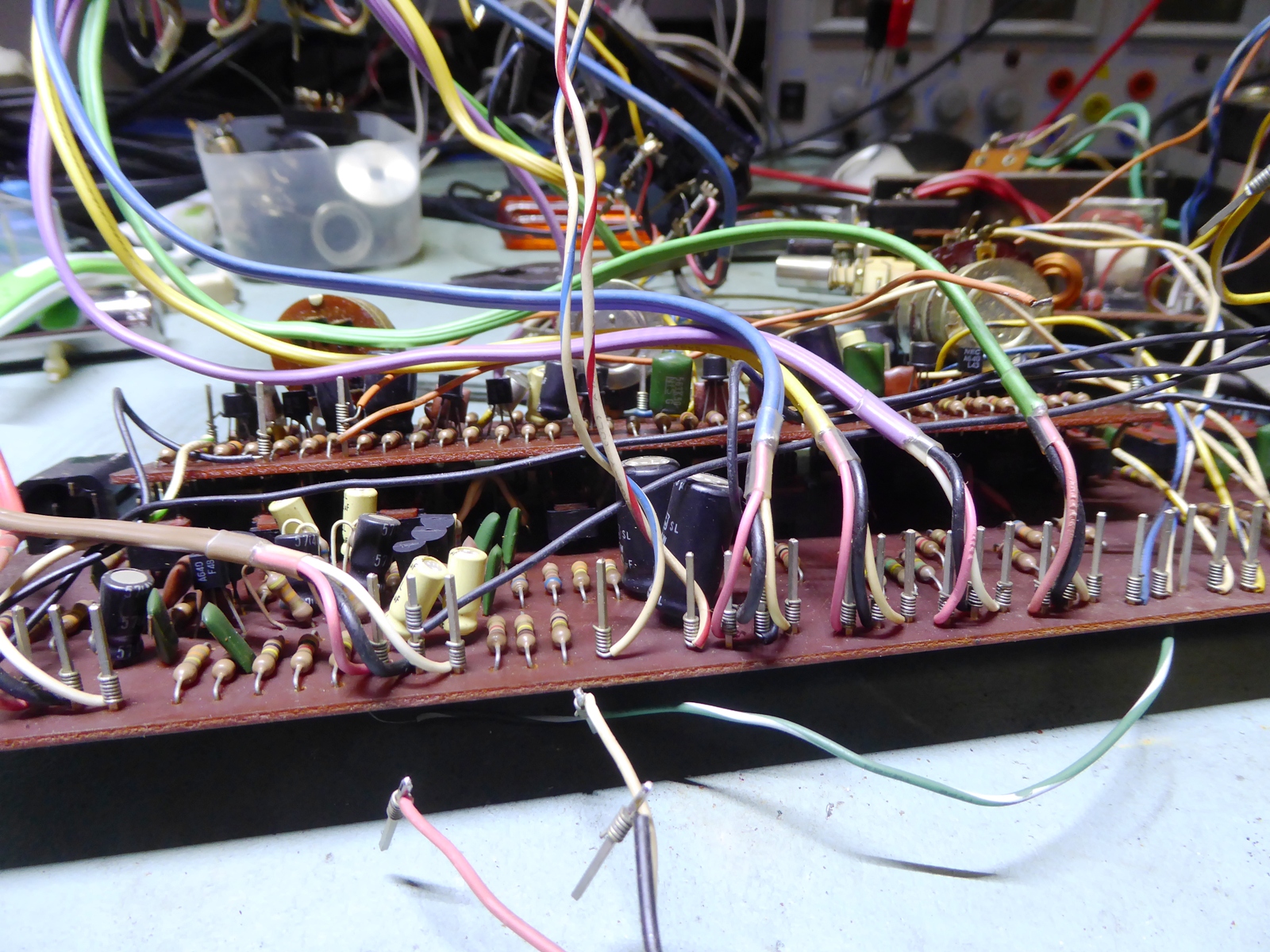

The following pictures are about the equalizer/switch board getting new components.
Old situation on the left, new situation on the right.

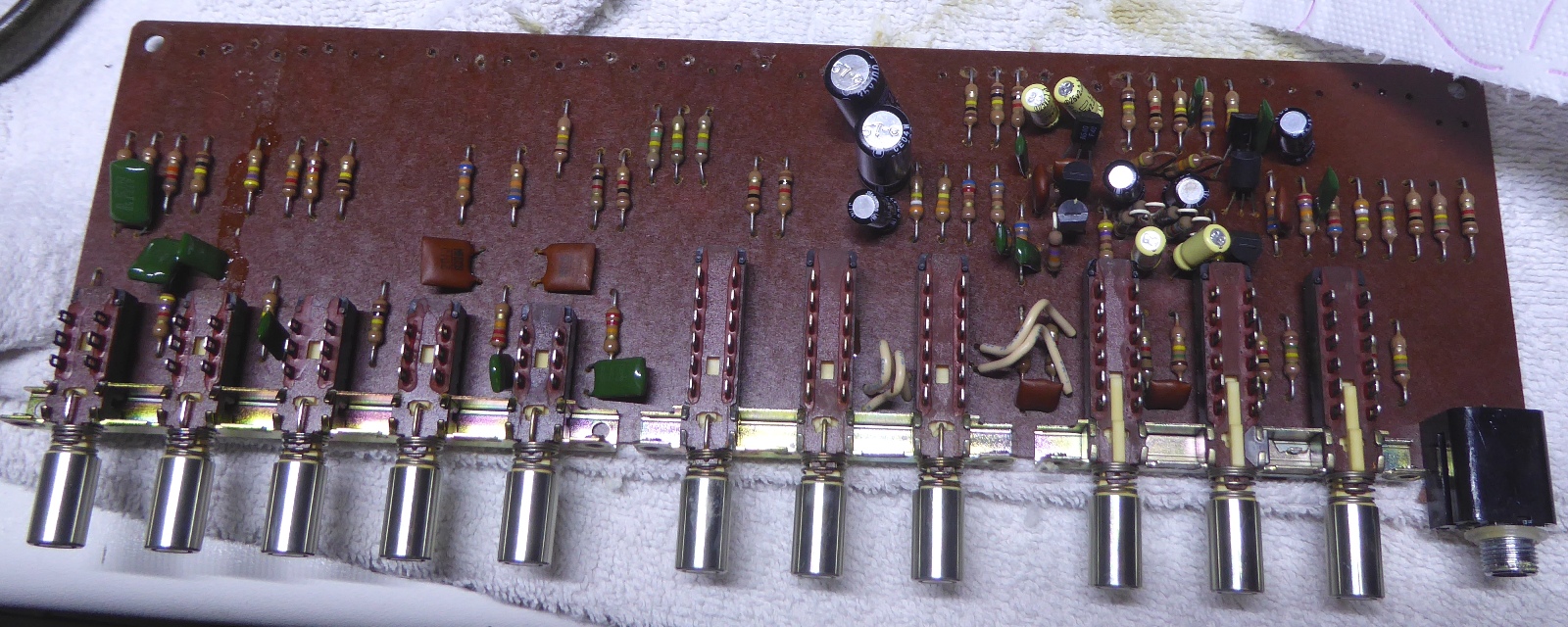


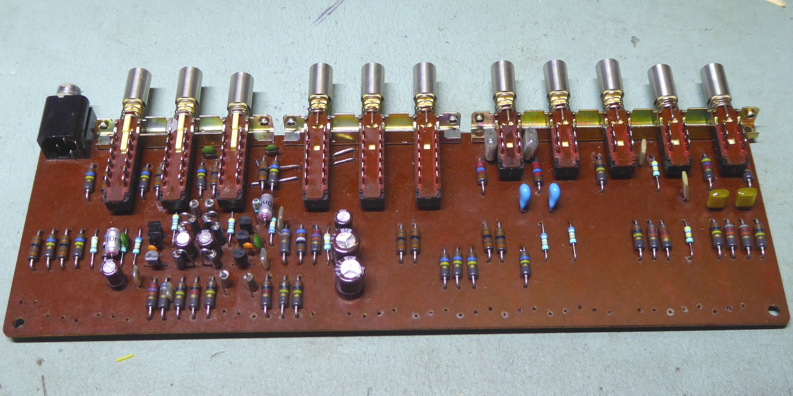

The following pictures are about the volume/mike mix board getting new components.
Old situation on the left, new situation on the right.

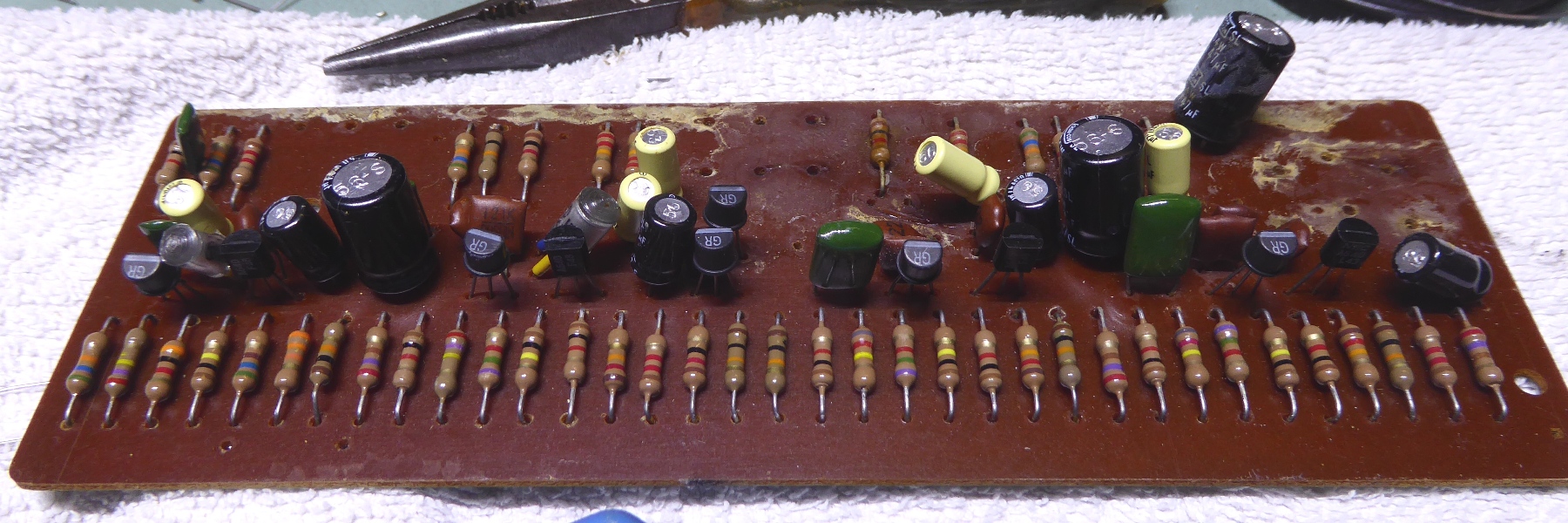


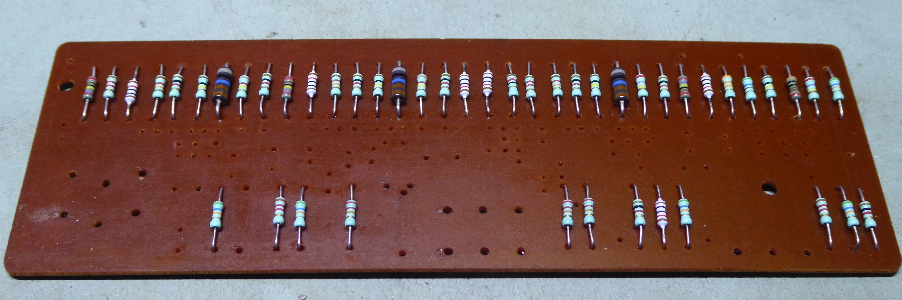


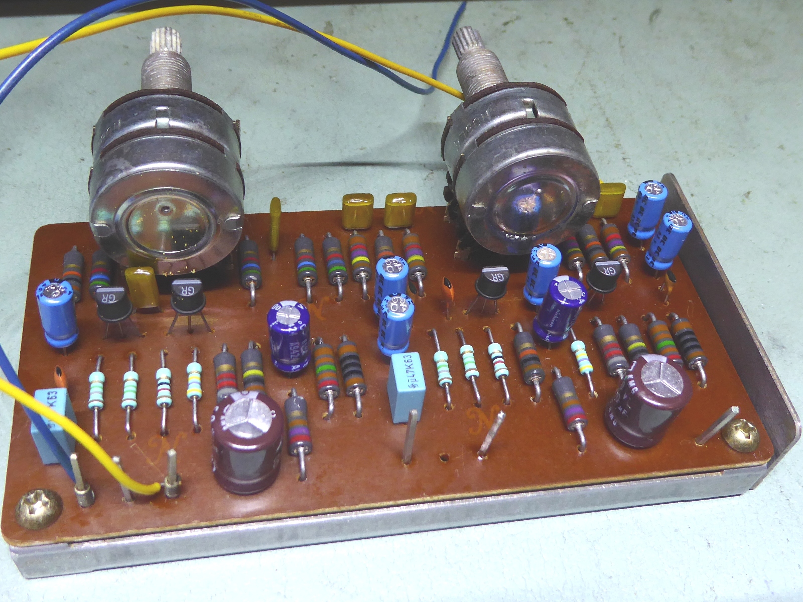
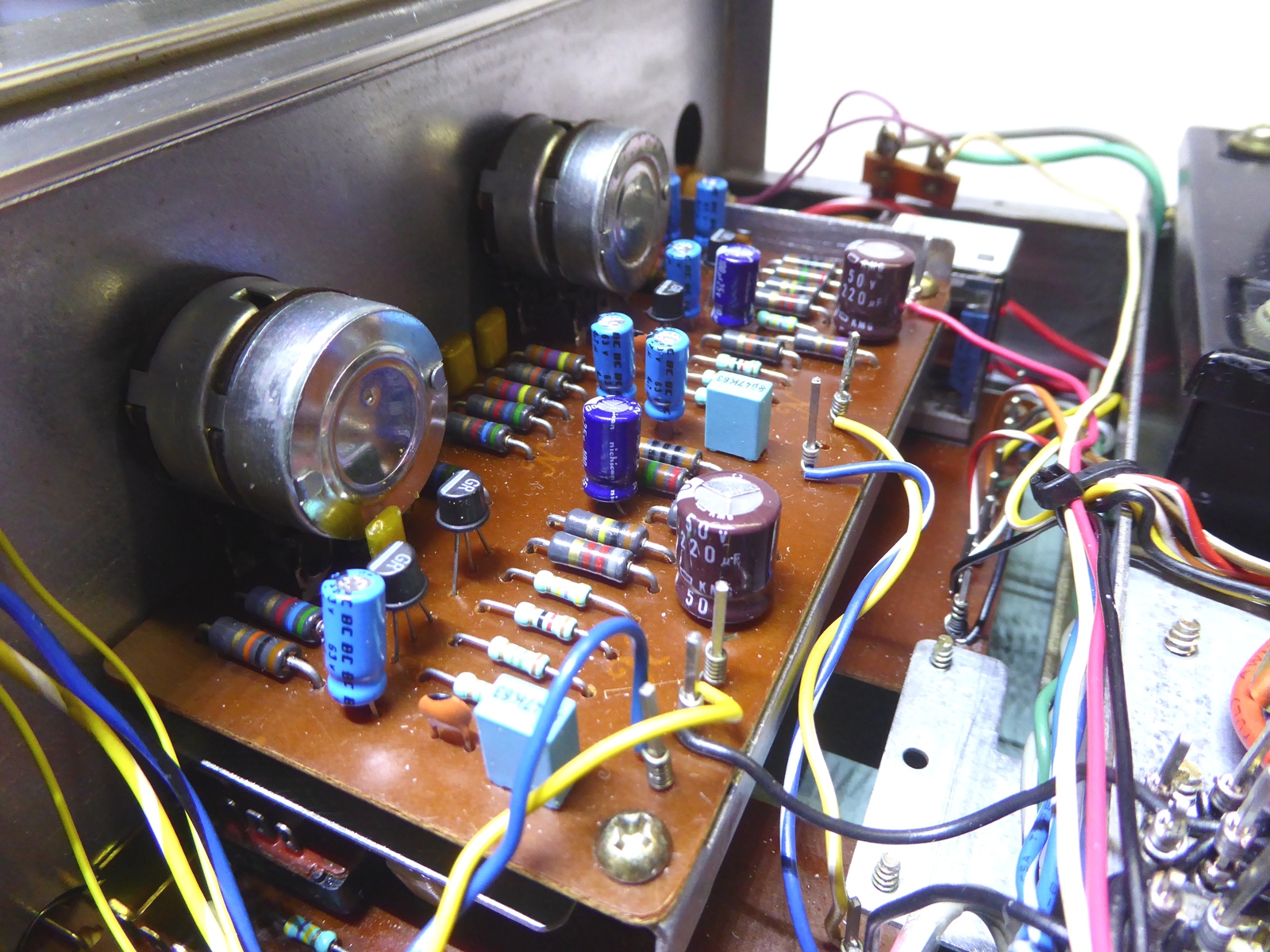
The already refurbished tone control board:





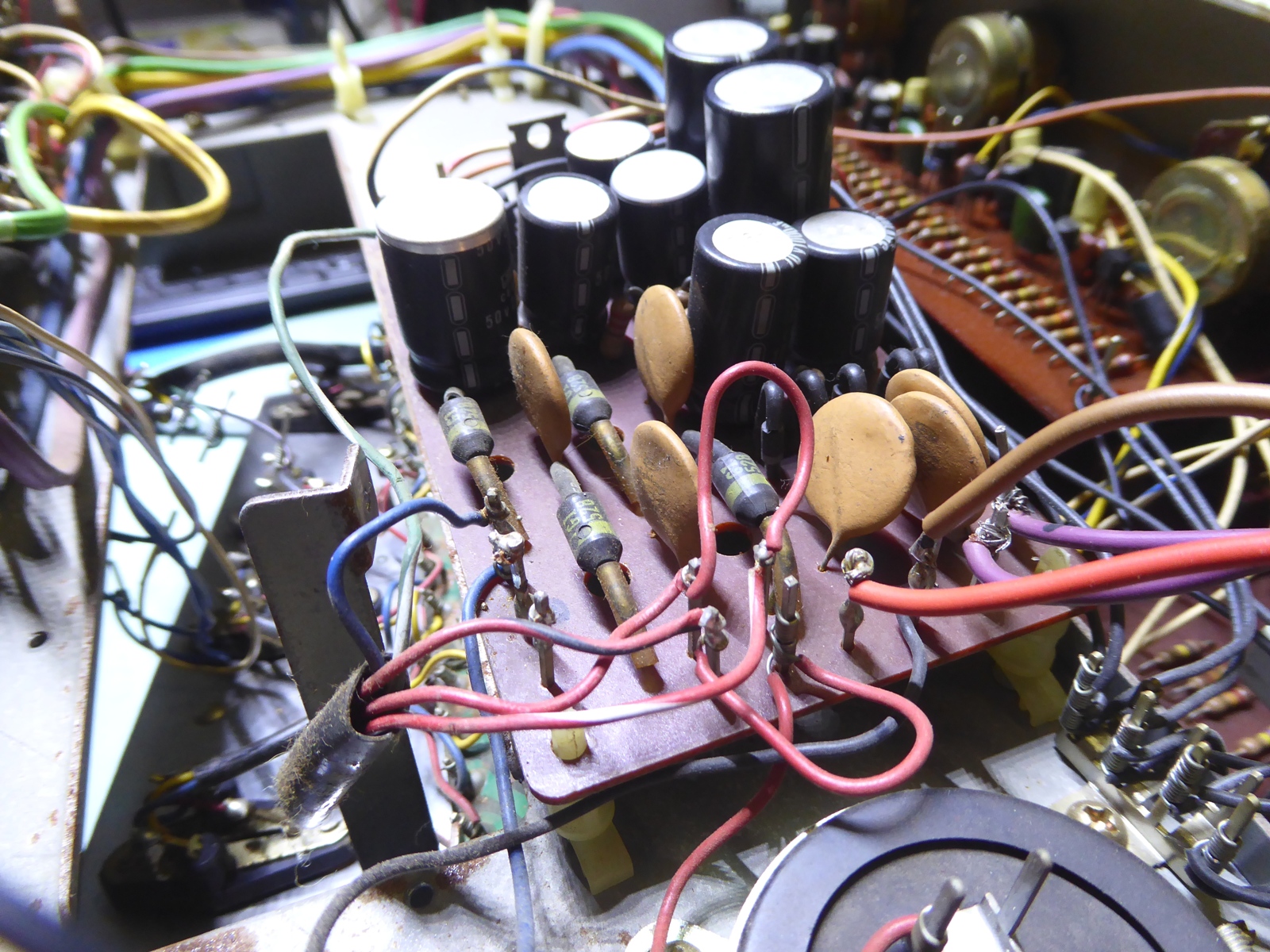
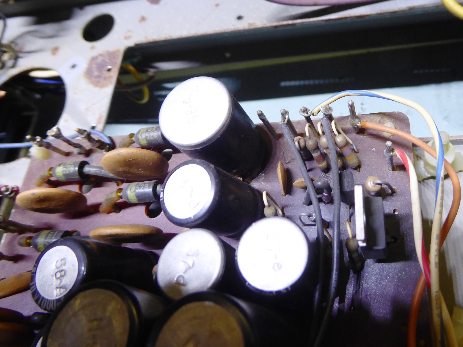
The power supply, and the protection card.

The power supply is rather blackened, it needed some cleaning up.
The power output transistor measured still good, however, it was replaced and now it has a heatsink to get rid of the undoubtly present amount of heat dissipated.
On the pictures one can easily see the trouble area.





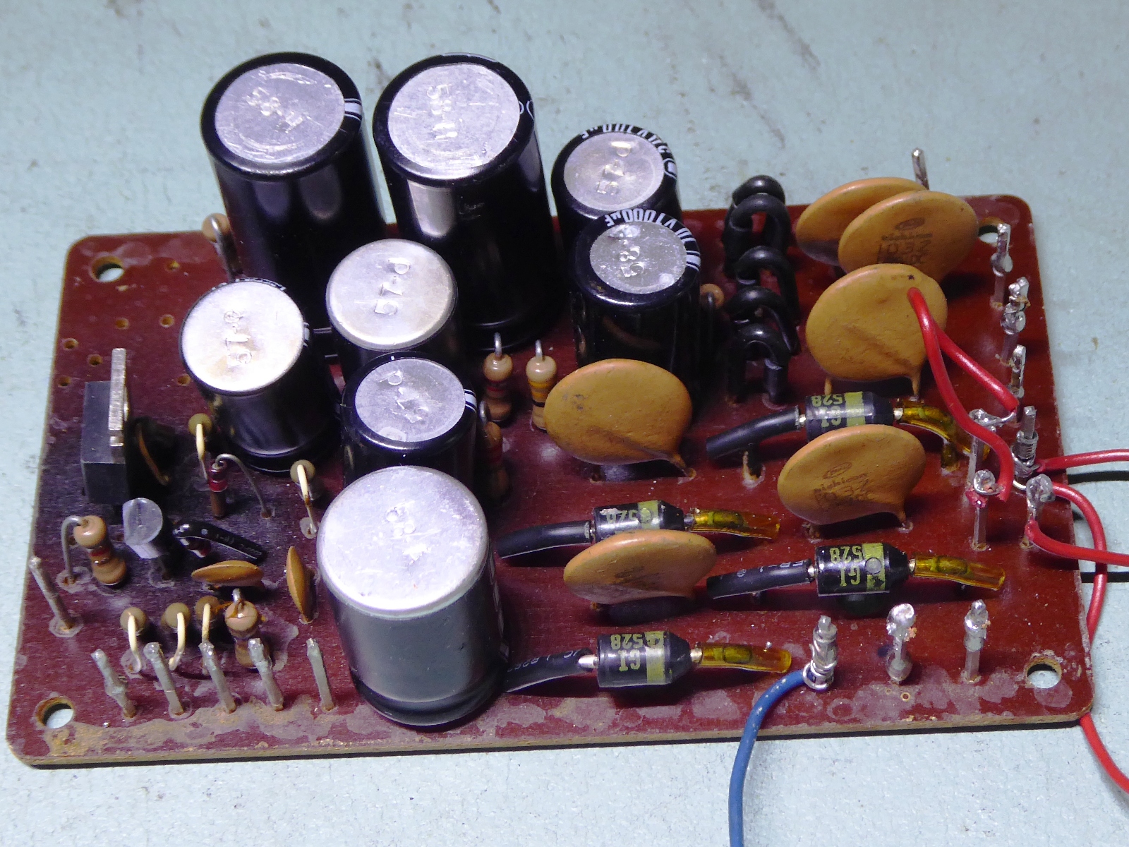


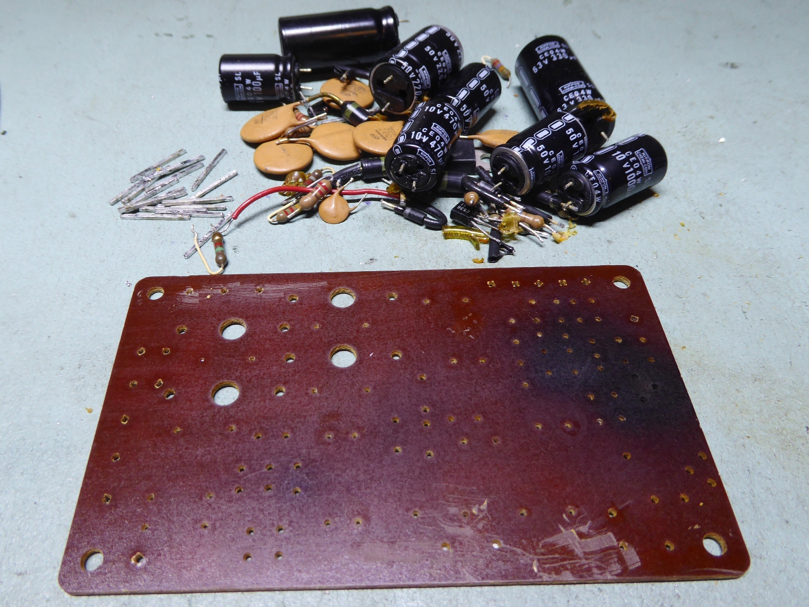

The renewed power supply mounted, new 10000 microfarad capacitors. To the right of the power supply board is the refurbished protection board.

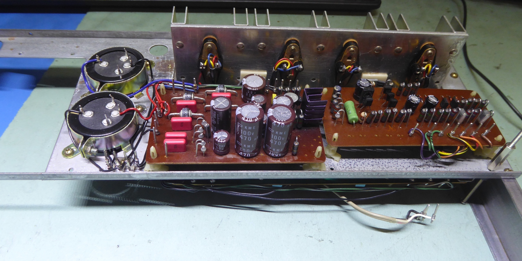


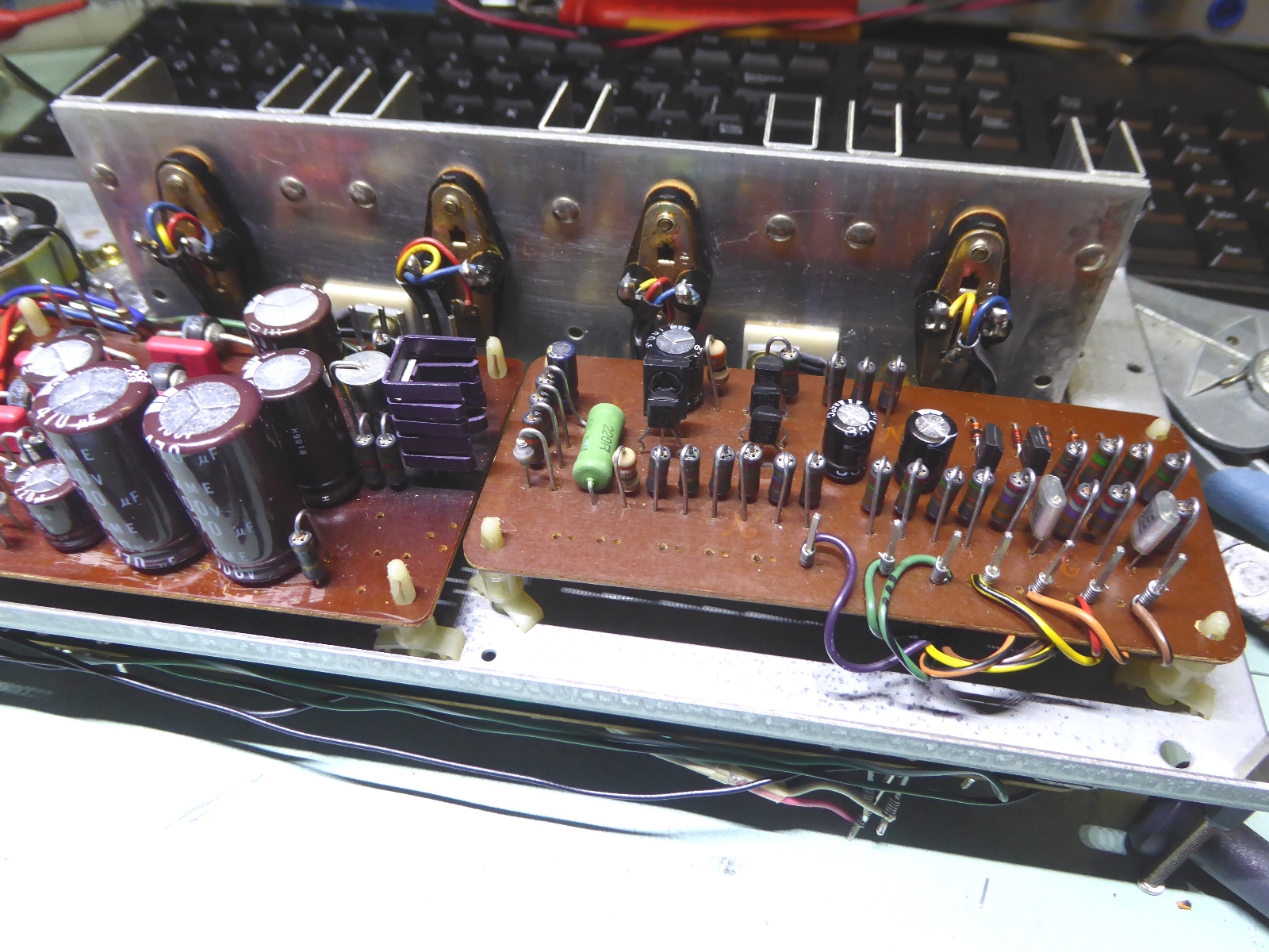


The power amplifier

The main power amplifier looked like a warzone, both channels did have burn marks and bad components, as the pictures show.....

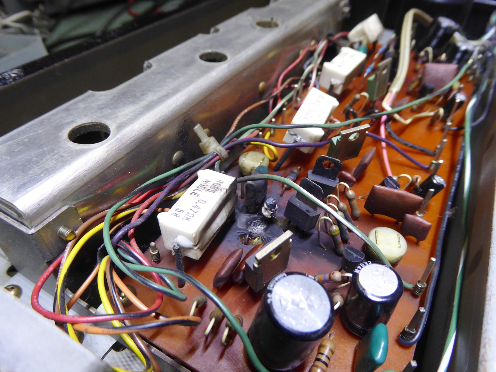


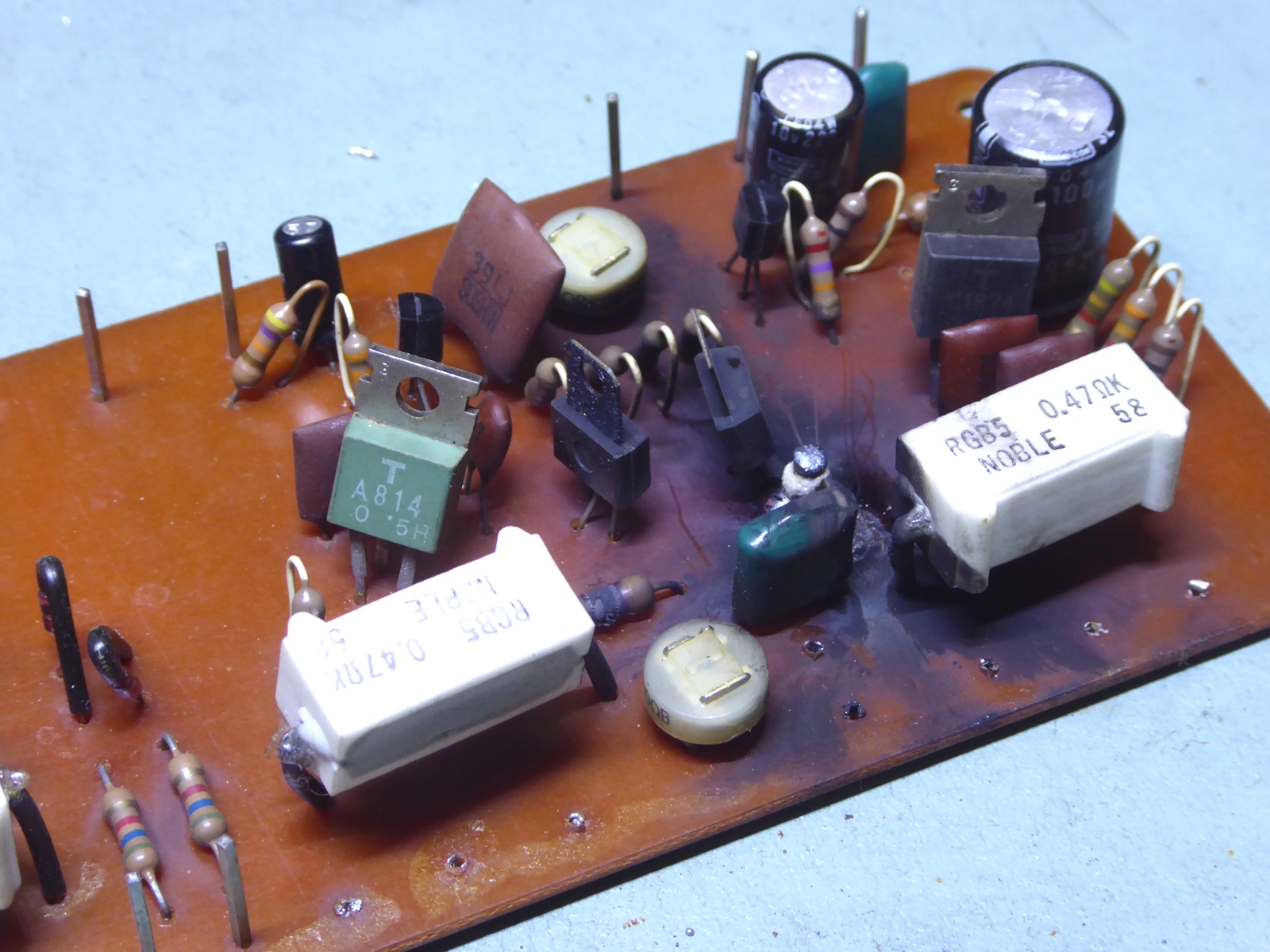


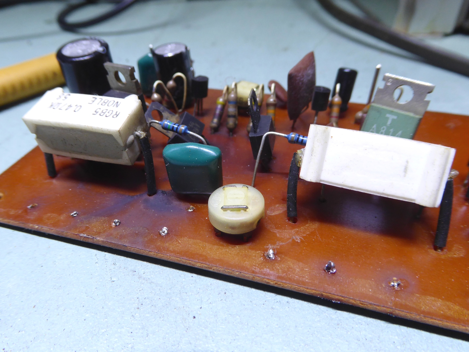

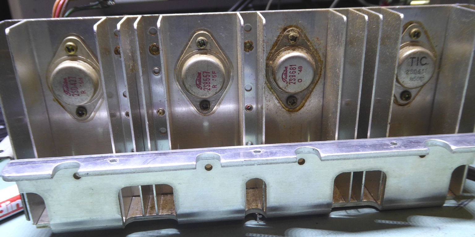
The old power transistors were all different from each other.


The main power amplifier empty card. All transistors were replaced, TO-5 type of transistors were used instead of the Motorola-type and the TO-220 ones.
The transistor mounting holes location in the card suggests it was designed to accomodate TO-5/TO39 transistors already, but the orientation is the wrong way around.
Therefore, the transistors I wanted to use did get their base legs moved to the other side below the plastic standoffs before mounting.
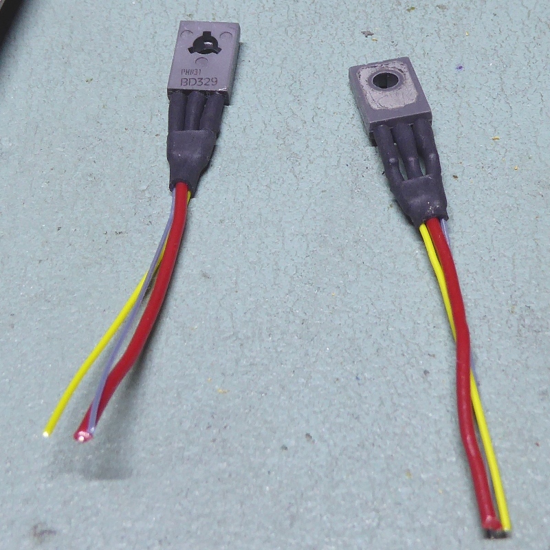
For reliability, I did get rid of the diode/NTC type of temperature sensing, I did mount a BD329 transistor as sensing element/VBE multiplier circuit.


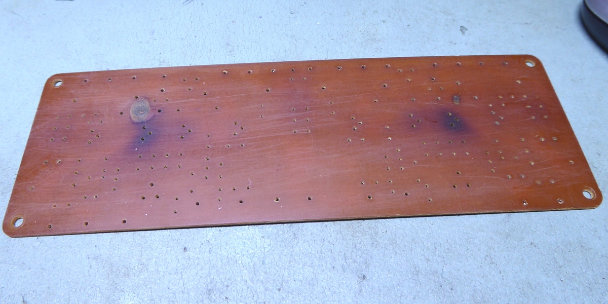


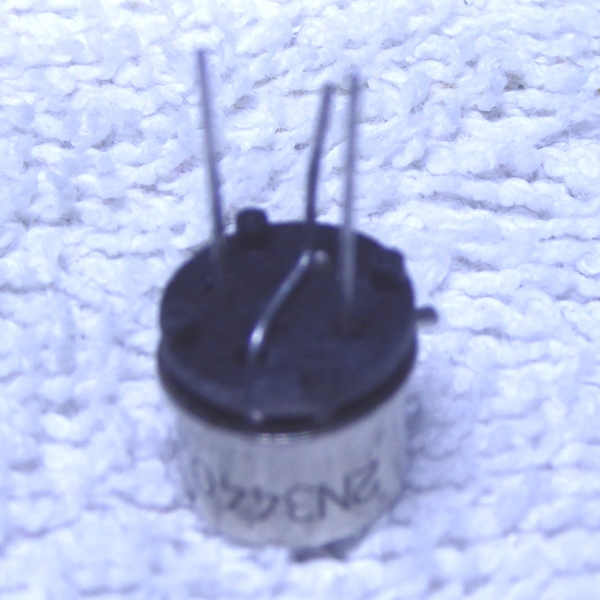



The circuit card was rebuilt, using the TO-5 / TO39 transistors probably makes it look more nice compared to when it was new.

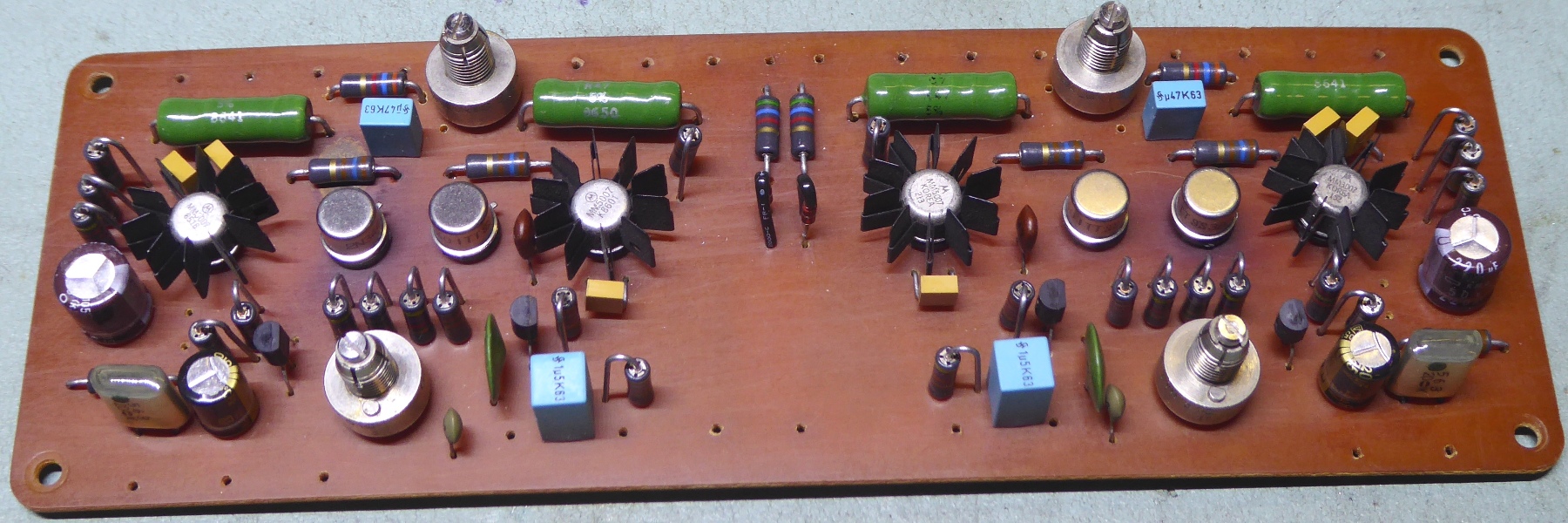

The wiring is a little bit tidier and the BD329 heat sensing transitors are mounted using a ceramic heat conducting pad, intended for TO220 devices.


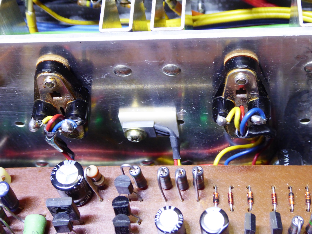

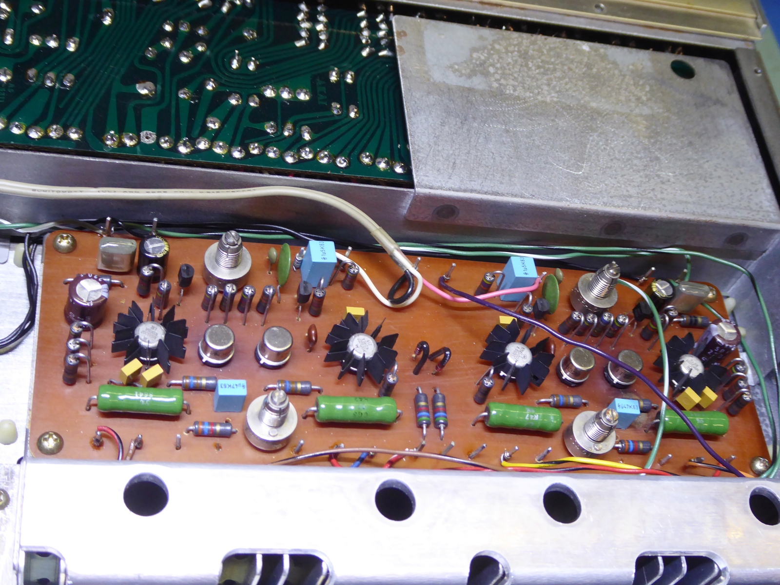

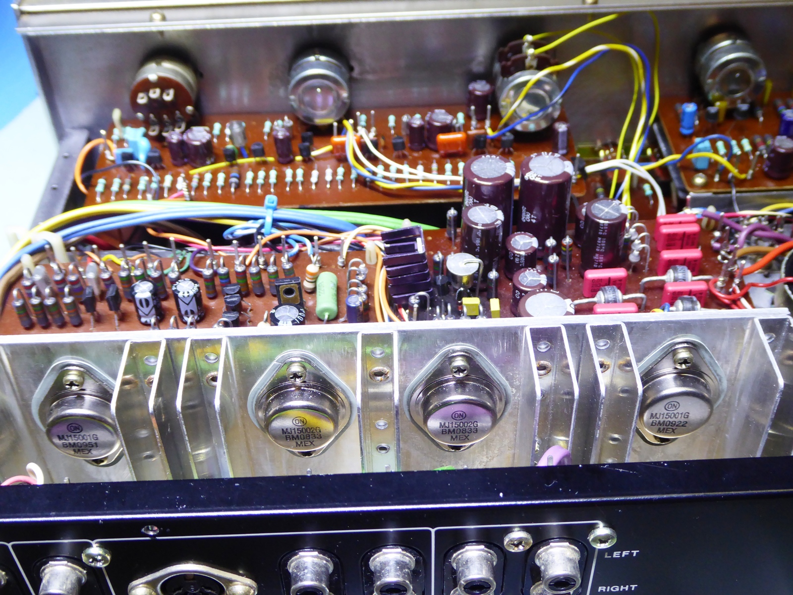
The new power transistors, and in the background the remounted other circuit cards.



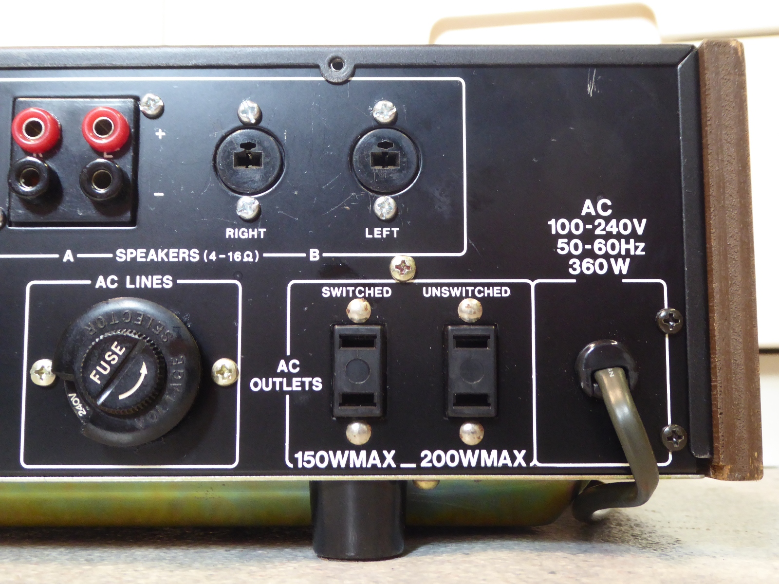
The special loudspeaker connectors were replaced using banana sockets.



Ga naar Gerards page / go to Gerards other pages ---->>> ![]()
