Ga naar Gerards page / go to Gerards other pages ---->>> ![]()

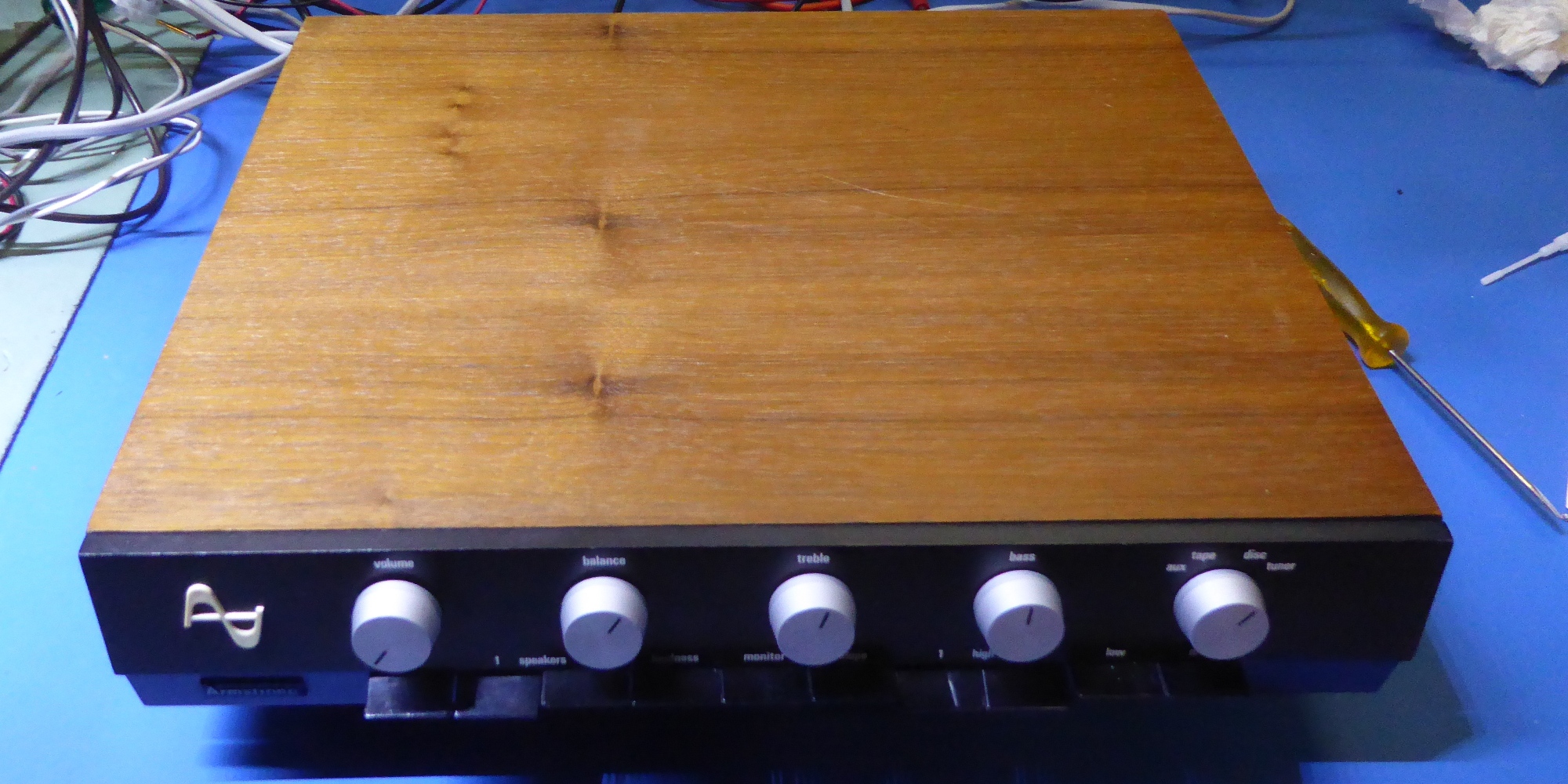
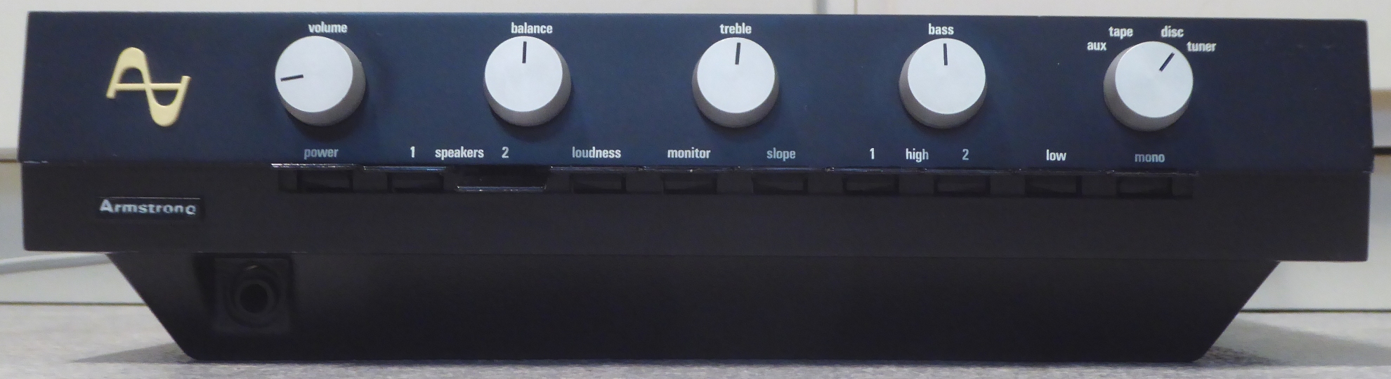
Armstrong 621 refurbishment / recap / modifications
![]() Gemakshalve is deze pagina alleen in het Engels geschreven.
Gemakshalve is deze pagina alleen in het Engels geschreven.
![]() This page is written using English language only.
This page is written using English language only.
It was having several severe defects and previous repairs were done by some audio shop, I needed several iterations of troubleshooting to get the amplifier to behave I want.
All electrolytic capacitors were replaced throughout the amplifier, just because of their age, measuring "still OK" or not.

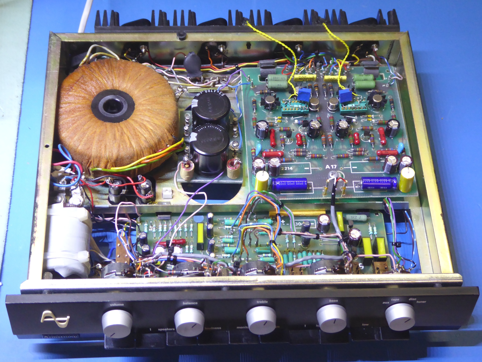
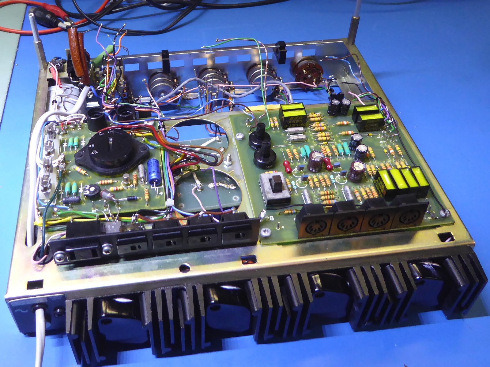
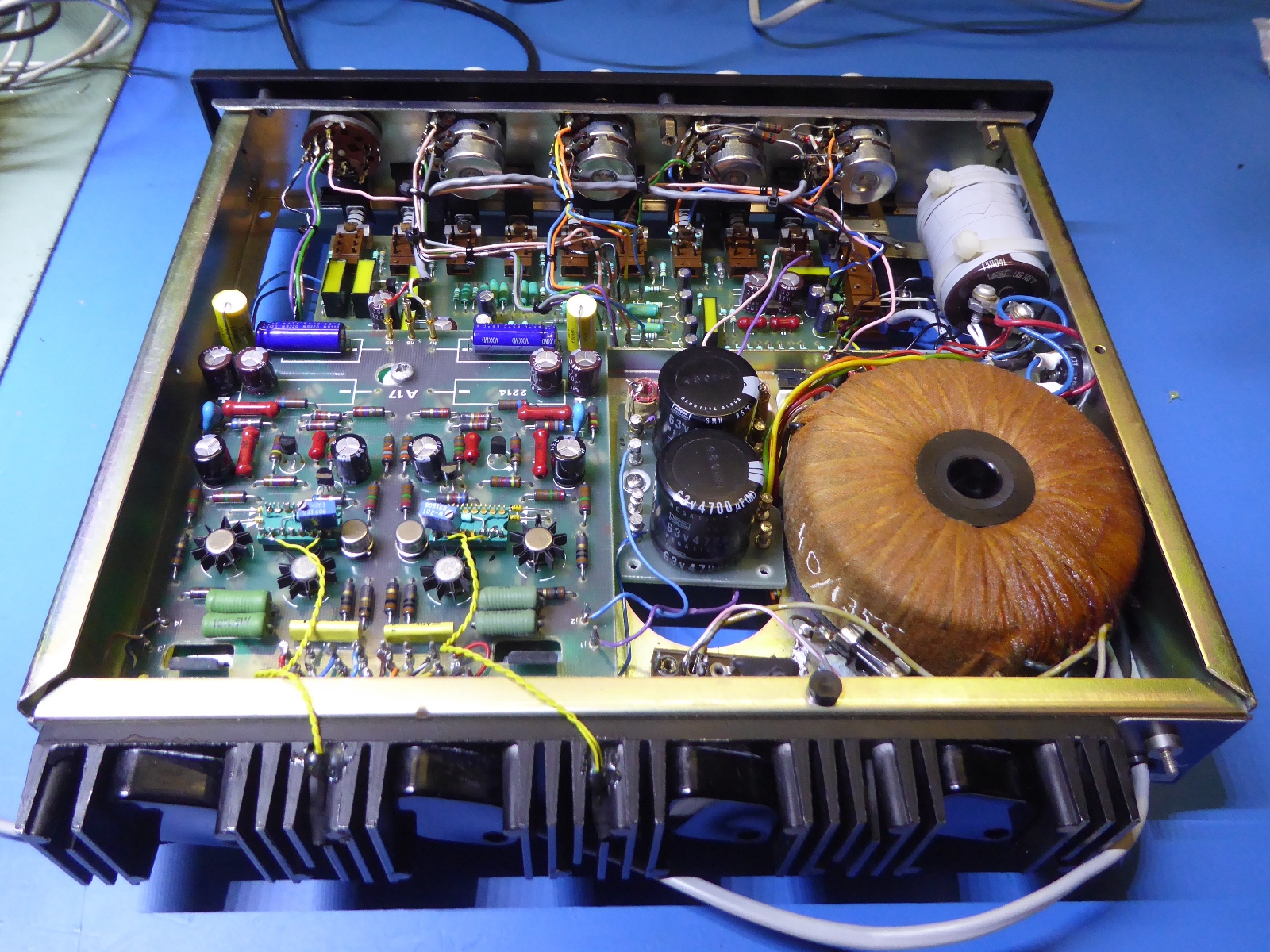
The power supply part of the amplifier
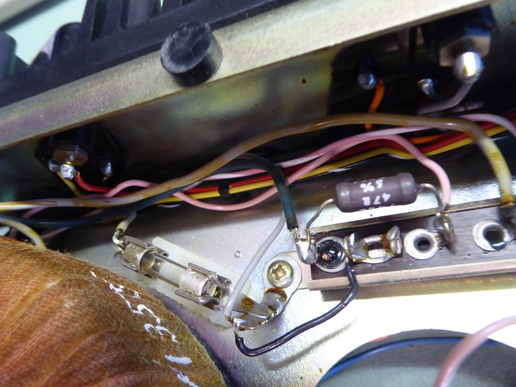
Initially, the start-up delay heated bimetallic switch was totally overlooked (it looked like a mounting strip)RTFM!!.
It caused hickups and odd amplifier behavior.
Erratically, I contributed this behaviour to some capacitance choices made on new electrolytic capacitors, it did put me on the wrong troubleshooting track.
I took the switch and heating coil from the back of the mounting strip, and the 47 Ohms resistor, as well. As a compromise, a 5 Ohms heat-shrinked NTC resistor was mounted. Also a little bit odd (and not according schematics) is the ground-referenced fuse of the power indicator lamp. It was taken away from ground and the defective and burnt lamp was replaced by two LEDs.
The power supply regulator/voltage selector card showed different diodes as a result of a previous repair, they were taken out.
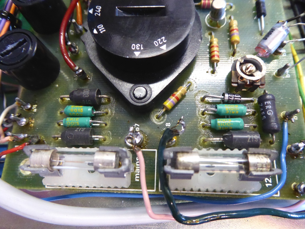
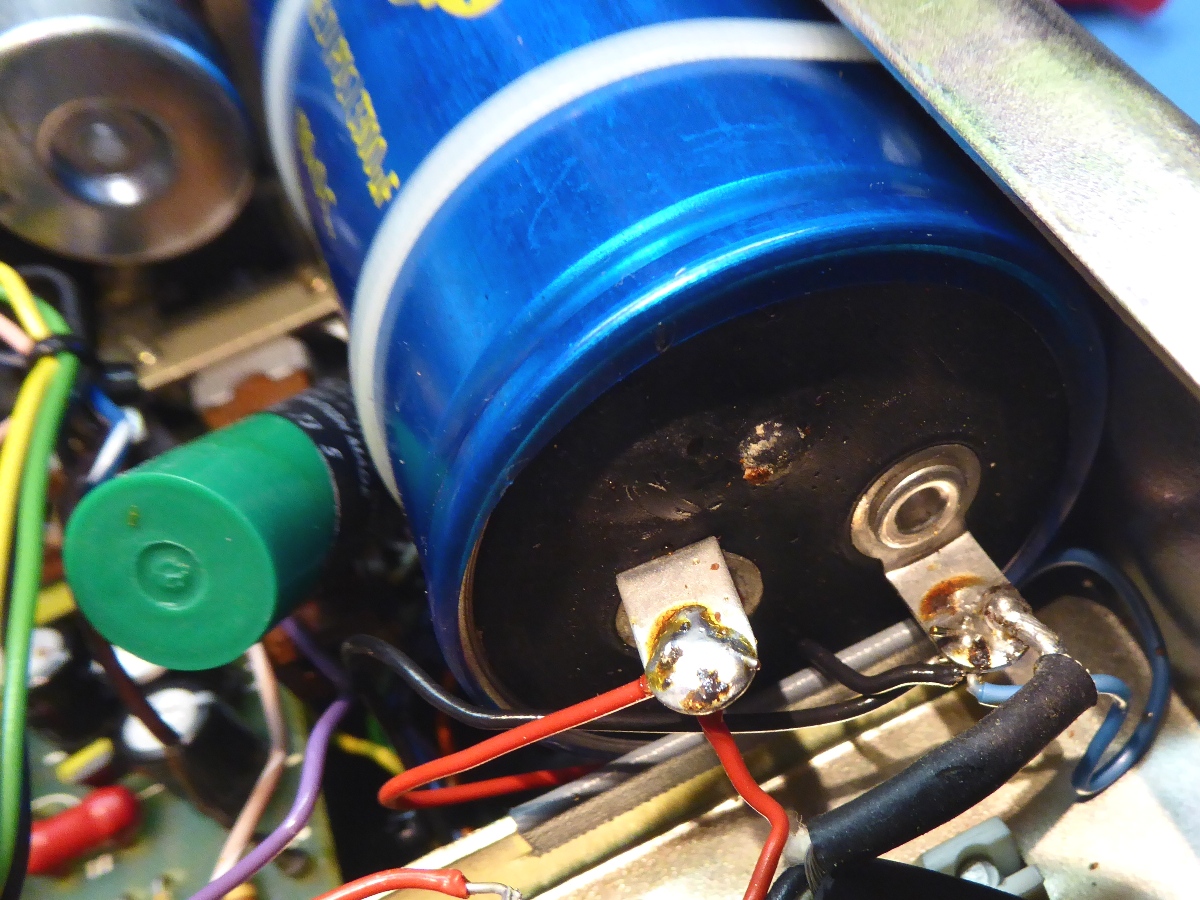
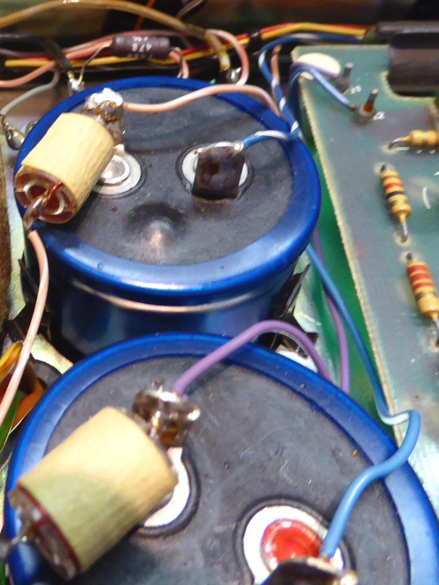
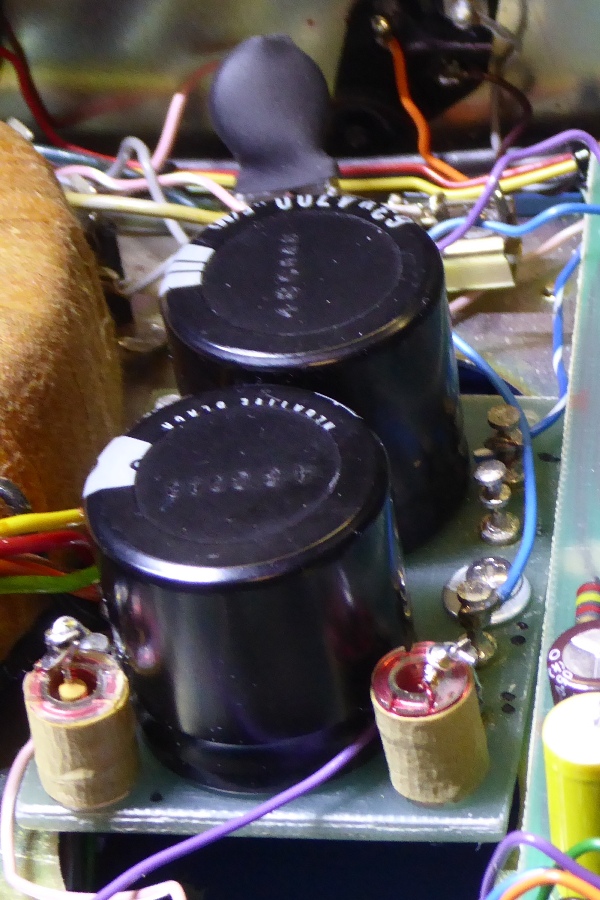
The power supply big smoothing capacitor showed evidence of venting.
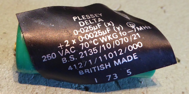
A small green dual filter mains capacitor was found, its tape left sticky debris all over, it was removed. No replacement was put in, as there is no room for safely mounting it.
It should be noted, the wiring is NOT according todays safety standards, and there is NO ROOM to rewire it properly using proper components and workmanships standards.
Instead of putting in more heavy diodes on the power board, it was decided to mount a bridge rectifier against the side panel.
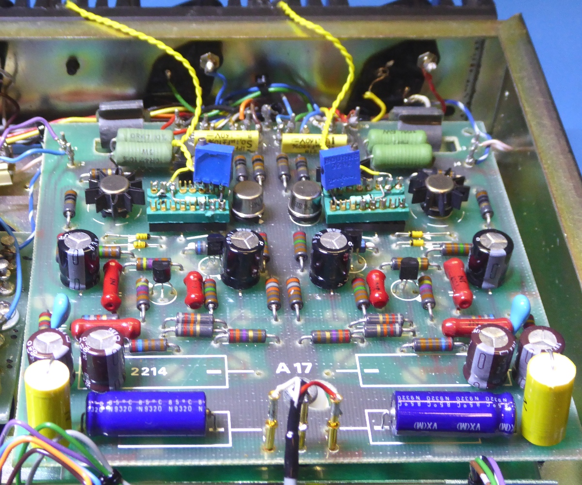
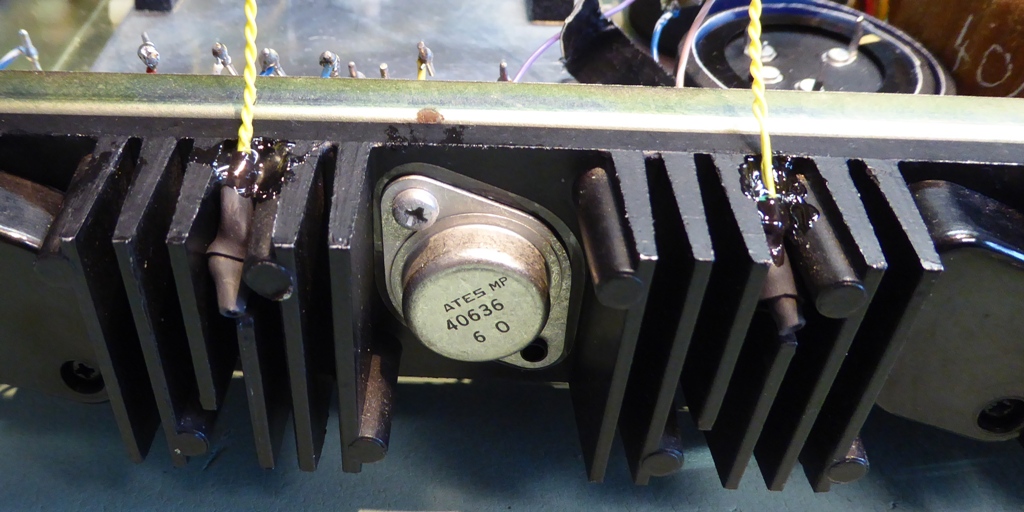
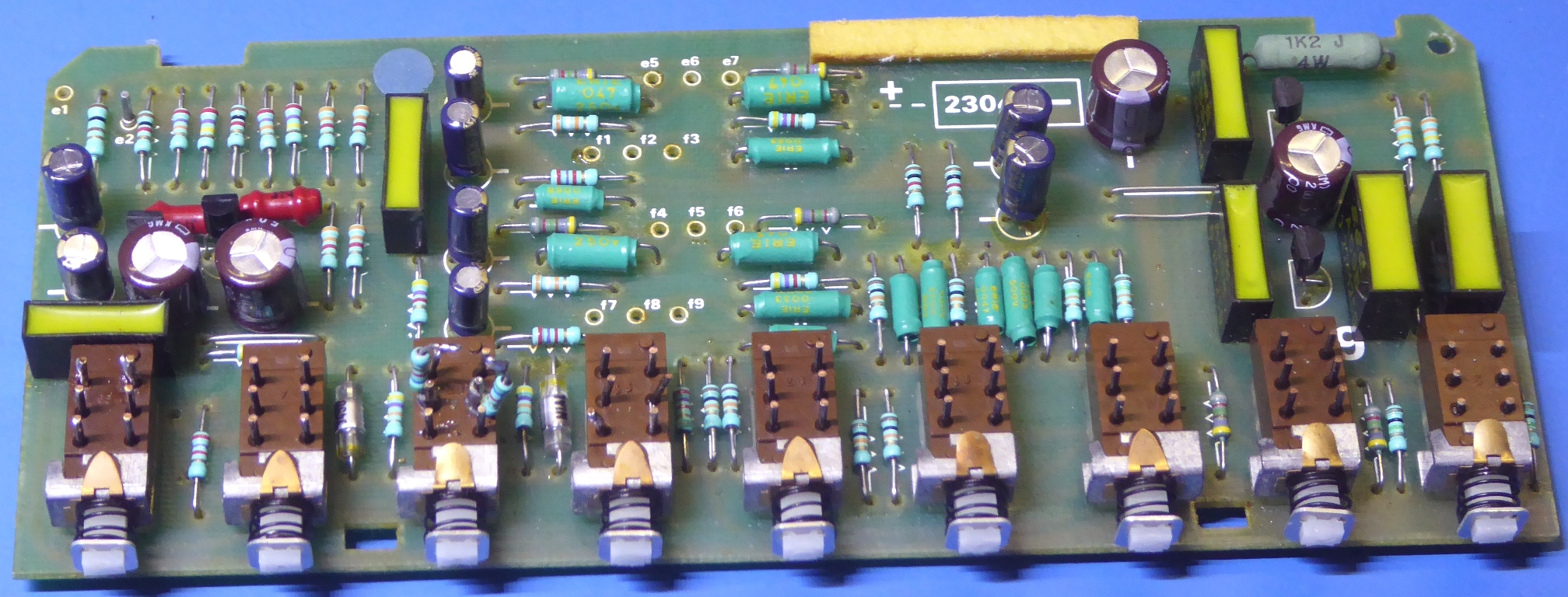
The main amplifiers The main amplifiers had very low HFE transistors, one was considered defective. According the schematics, the main output transistor emitter resistors were supposed to be 0.5 Ohms, they measured 0.7 Initially, the marking on them was overlooked, as they indeed appared 0.68 ohm types. As also the big TO-3 transistors were replaced by high-power 2N5631 ones, I left in the replacement resistors. Also new small signal transistors were put in, and new capacitors. The big axial capacitors on-board were not on hand, so holes were drilled to accomodate smaller replacements. Because the amplifier being vulnerable for thermal runaway, it was decided to mount an IC socket and find a solution for it. It was decided to opt for mounting NTC resistors in between the heatsink fins using the yellow wiring, Bias is set at around 40 milliamps. The amplifier card did get nice CGW metal film resistors
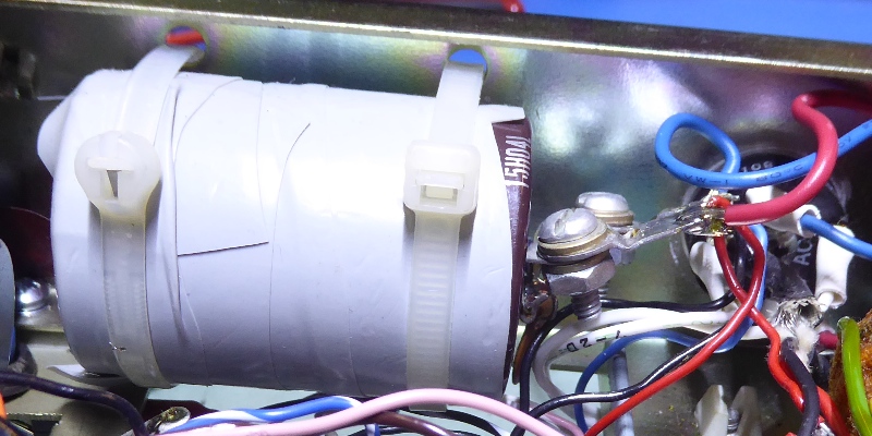
The big old signal ouput capacitors did not look too good, as one did have its vent hole bulging. They were replaced by mounting two capacitors on a circuit card. It also accomodates the series coil/resistor network on the outputs.
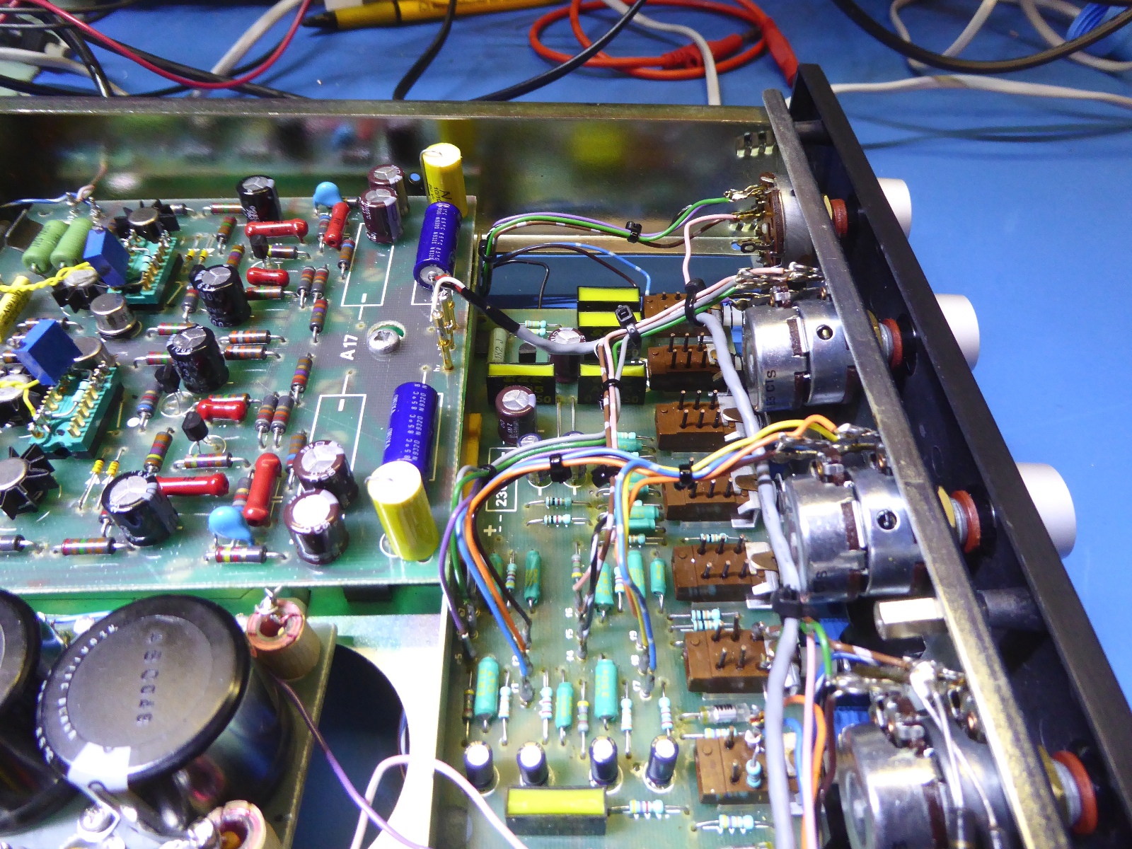
The pre amplifier
The preamplifier did behave erratically because of a volume potentiometer tracking difference.
This problem has been partly resolved by using parallel and serial resistors, providing a more acceptable behaviour.
As initially it was not clear if the poor tracking was the only problem, the preamplifier/tone board was taken out for refurbishment, also.
It did get new transistors and Philips SFR25 metal film resistors, I like the amp to be able to challenge any other 621 amps on the market, as one day I may sell it.
The long wire between the volume potentiometer and the main amplifier is replaced by a shielded one. Apart from electrolytics exchange the board carrying the DIN-5p inputs was mostly kept as it was.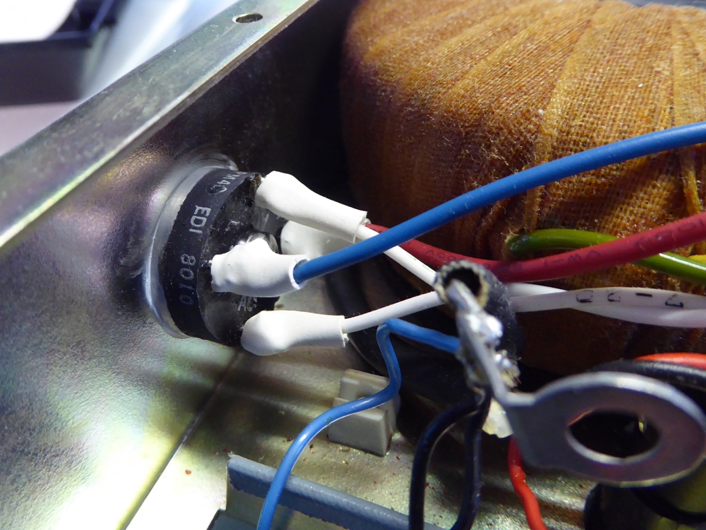
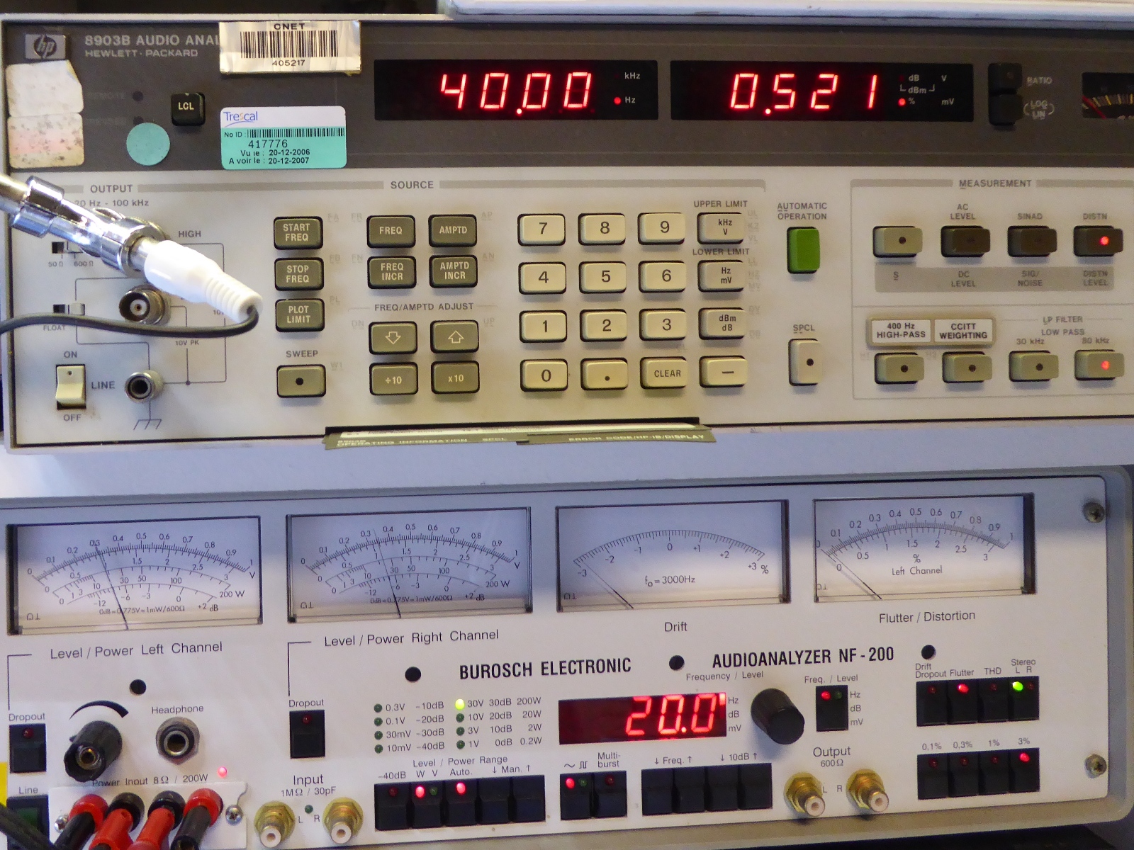
Testing etc
During testing, it is evident clipping starts occurring soon above 30 Watts continous sine wave power. Because of using output capacitors, low frequency distortion was interesting, at 40 Hz it is around 0.5%, which is satisfying.
As the amplifier is not symmetrically powered, overdriving it will have a lot of influence on the power supply and amp DC behavior and it will create (infra)sonic problems if steered too hard.
There is a very interesting article on this on the internet, see here at Elliott Sound Products.As a side note: it is not recommended to provide a sine wave to drive old amplifiers to full power when not restored or in good condition, as many will not survive.
At moderate levels at different frequencies, distortion is around 0.2 % at a first glance, although no care is taken to clean up or optimize wiring and environment (led lighting SMPS etc close by).
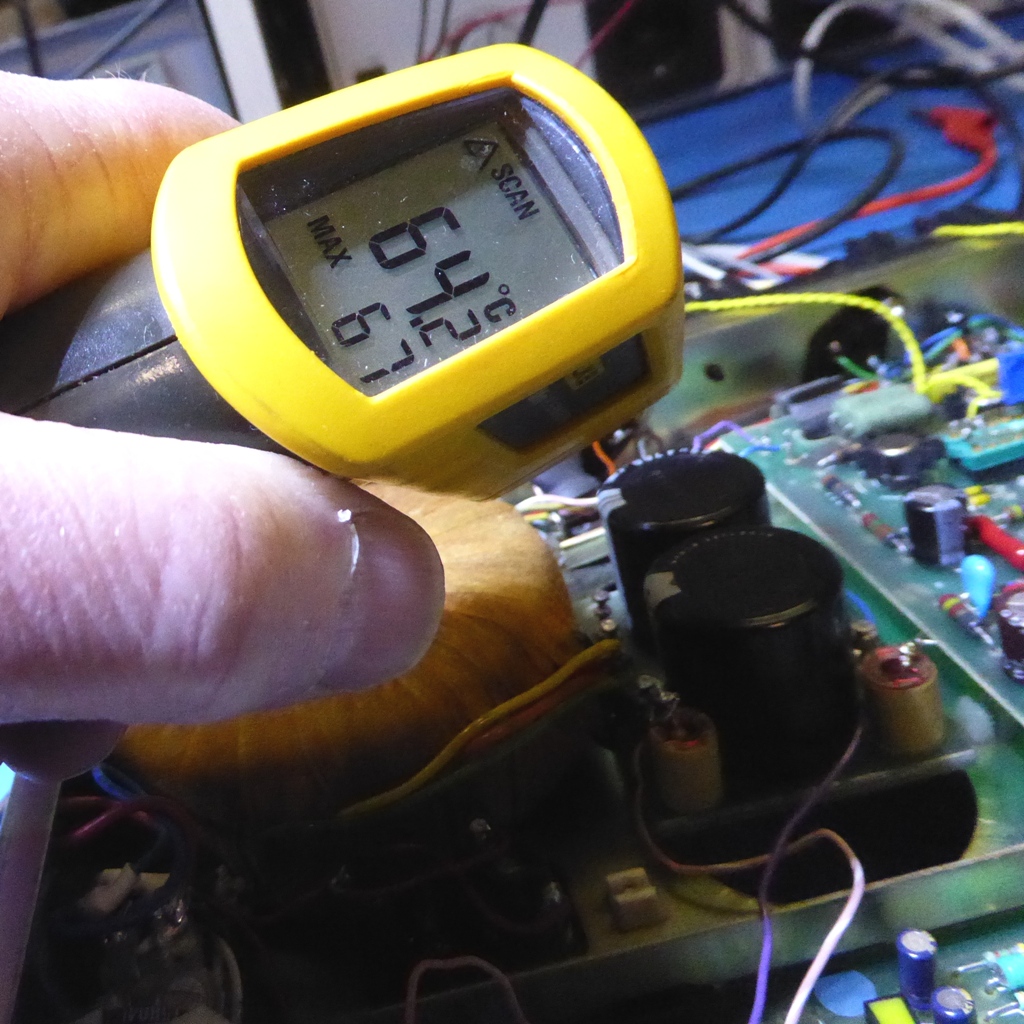
During the testing, partly at full output continuously, it was found one of the bolts of one output transistor did hit 64 degrees Celcius, and the whole heat sink was over 50 degrees. I presume, this amplifier would not survive it in stock form and would have gone up in temperature even more without my modification.
After turning the power down it appears bias current is lower than set initially, so there is no thermal runaway to be expected.
Go to my 2021 British addition, the nice Armstrong 521...
Ga naar Gerards page / go to Gerards other pages ---->>> 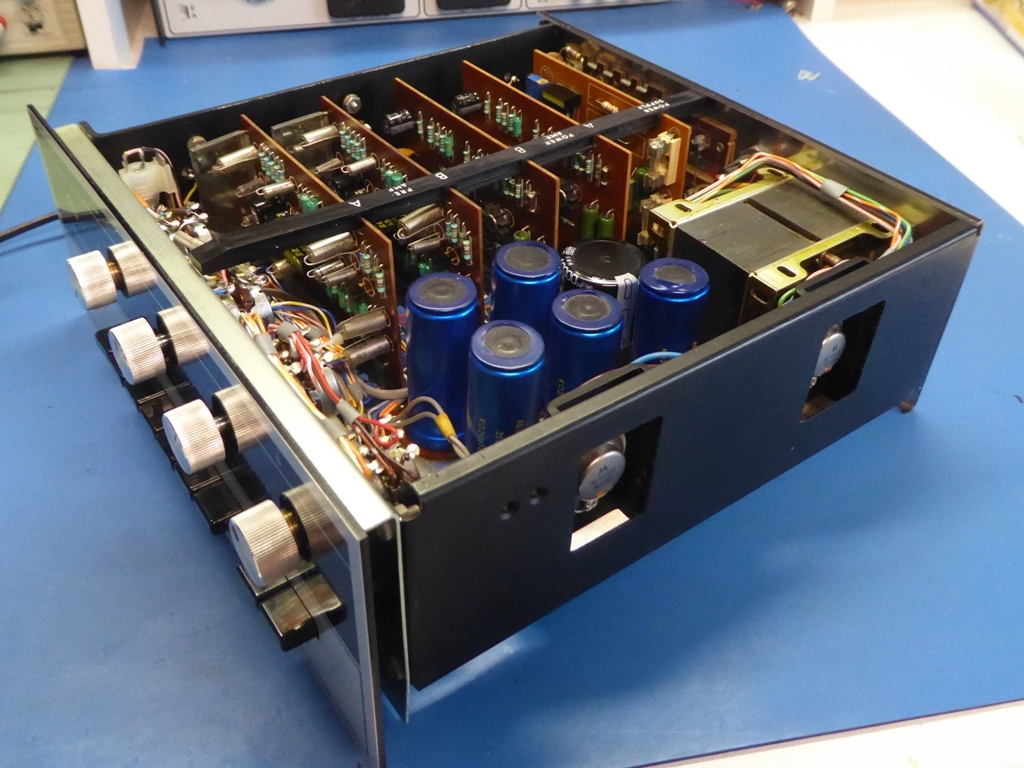
![]()