
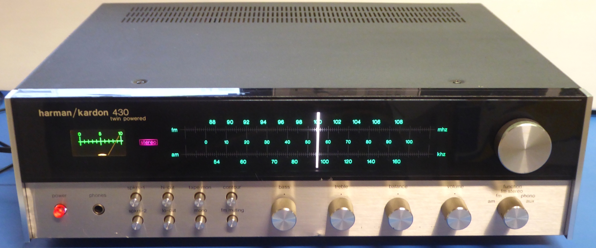
Harman-Kardon 430 refurbishment October, 2022
This HK430 was sold in 2023, I traded in a defective HK75+ which will be a future project, and some money paying for some new electronic parts for the next projects.
Gemakshalve is deze pagina verder in het Engels geschreven.
![]() This page is written using English language only.
This page is written using English language only.
This Harman-Kardon 430 still worked, it has some wear and tear signs.
Just because of the restoration hobby, it was decided to renew it, anyway.
I like it because of the straightforward design, the layout makes it easier to refurbish compared to over 50% of other receivers, it is just "a piece of cake"

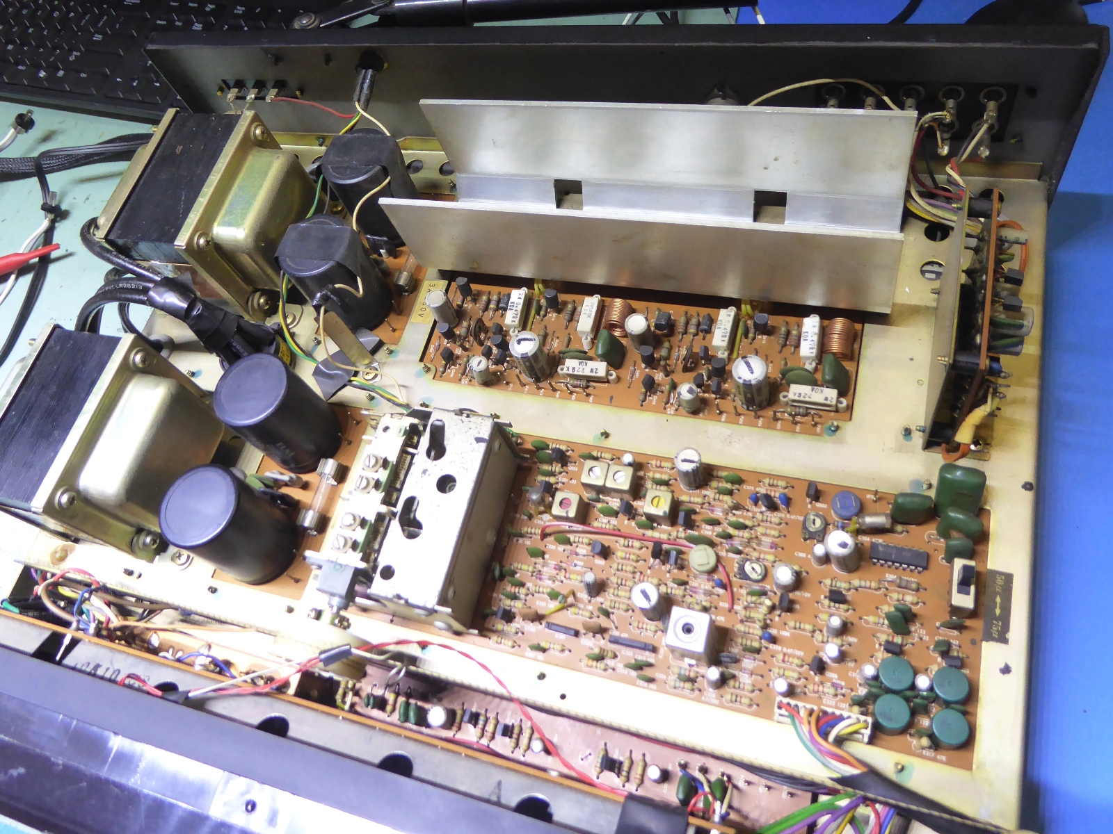
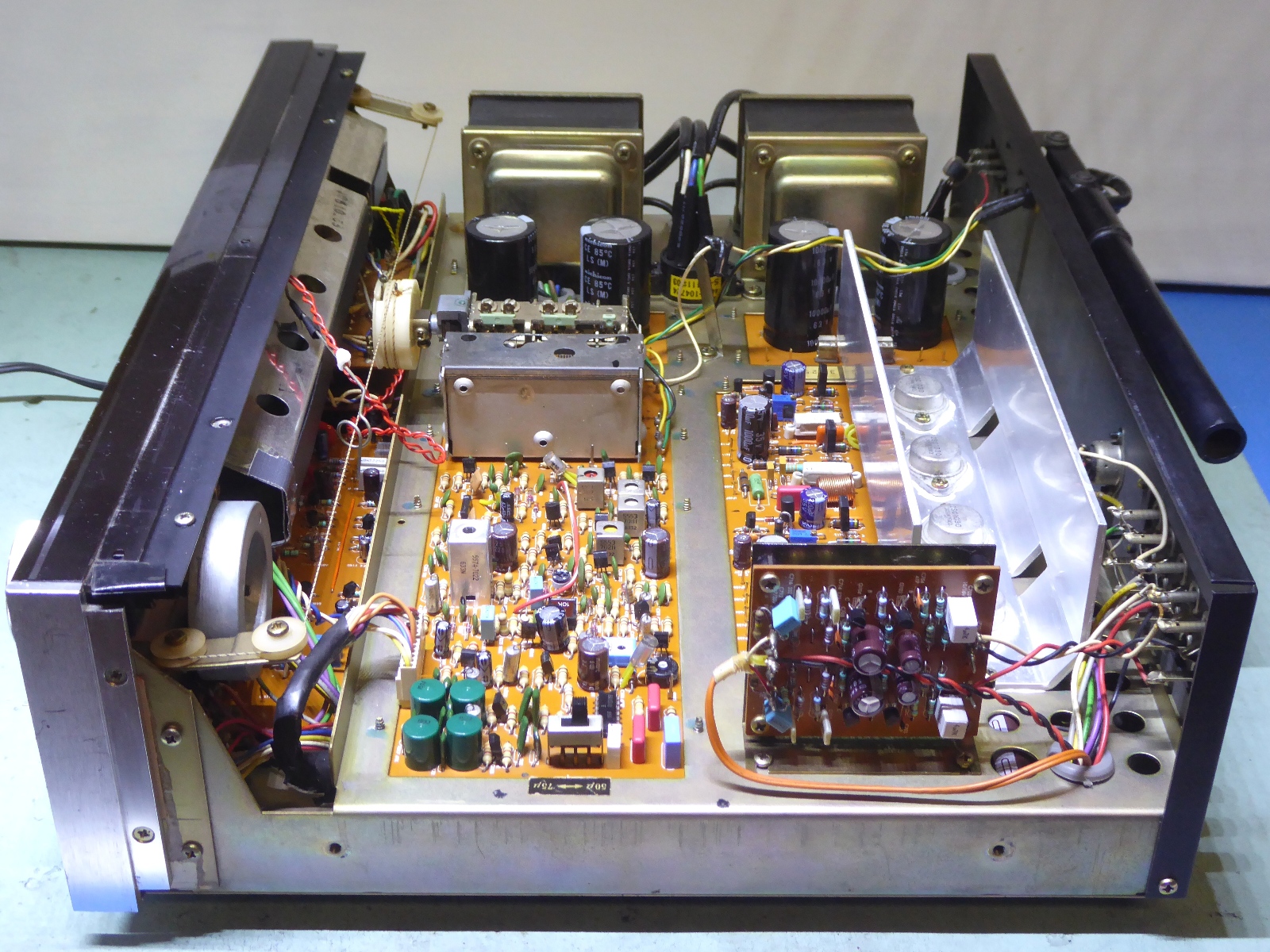
The innards of the not-yet-refurbished receiver from the top.
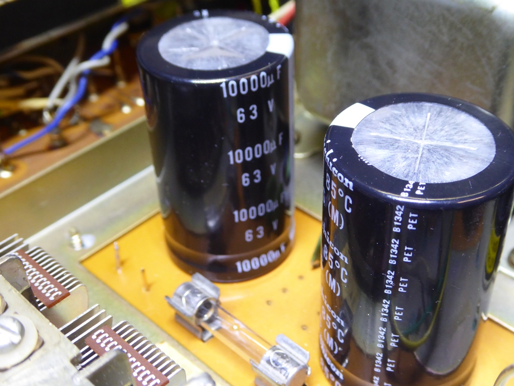
The Harman-Kardon 430 power supply
The power supply incorporates two transformers, each supplying one of the main power amplifiers, much alike the famous old "Citation Twelve" amp, which was still built in USA.
One of those also supplies two small regulated power supplies, the other also supplies the lighting bulbs present.
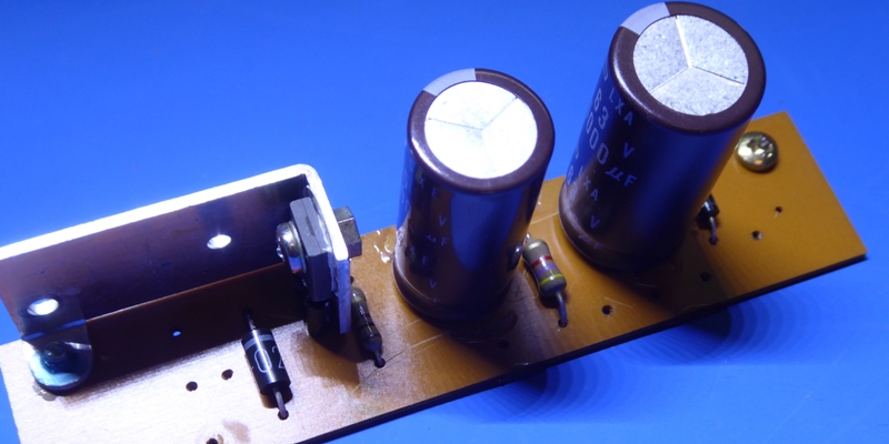
Whereas the intention was to use larger smoothing capacitors, it was decided to mount two bridge rectifiers on the back of the capacitor mounting circuit card.
There was no room on the top.

The big capacitors are 10000 microfarads now, the small boards schematics differ but the circuit cards themselves are both the same, having different component mounting options.
As there is no designation on the cards, care must be taken to use the proper parts orientation.
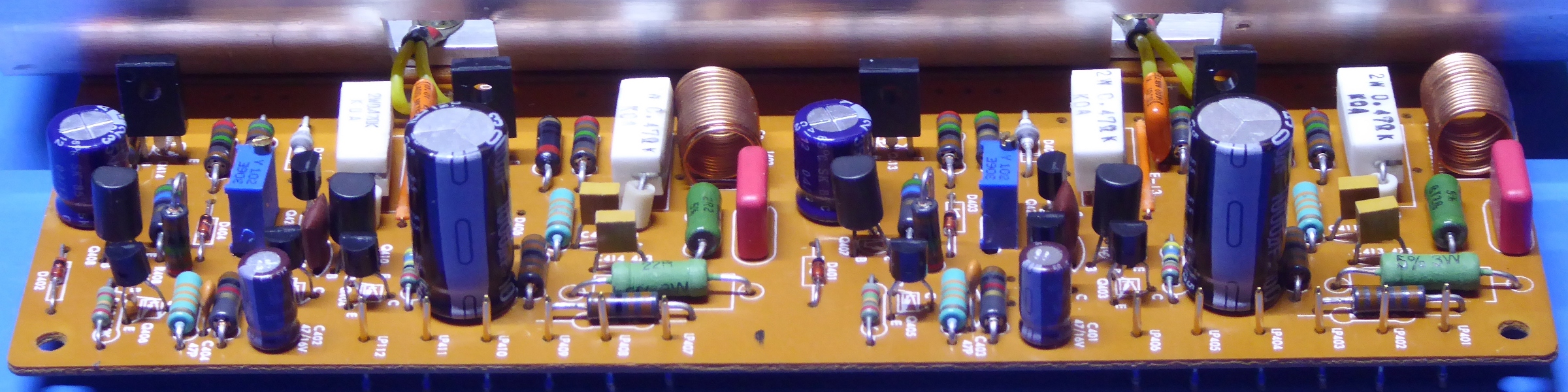
The power amplifiers board
Evaluating the power amplifiers, it appeared well known suspect small Hitachi transistors 2SC1345 were in, they were replaced.
The big current output transistors appear to have high enough HFE, and while the voltage/max power is limited, them 2SC1030 were retained.
To make sure the output circuit able to deliver enough current at all circumstances, the driver transistors of these were replaced by high-HFE KSA1220/KSC2690.
Usually, I modify such output amplifier arrangements and incorporate the famous "Baxandall-diode modification", but Harman Kardon did already put it in by design.
Still, I replaced the diode by a new one, as I simply do not like black corroded diode wires.
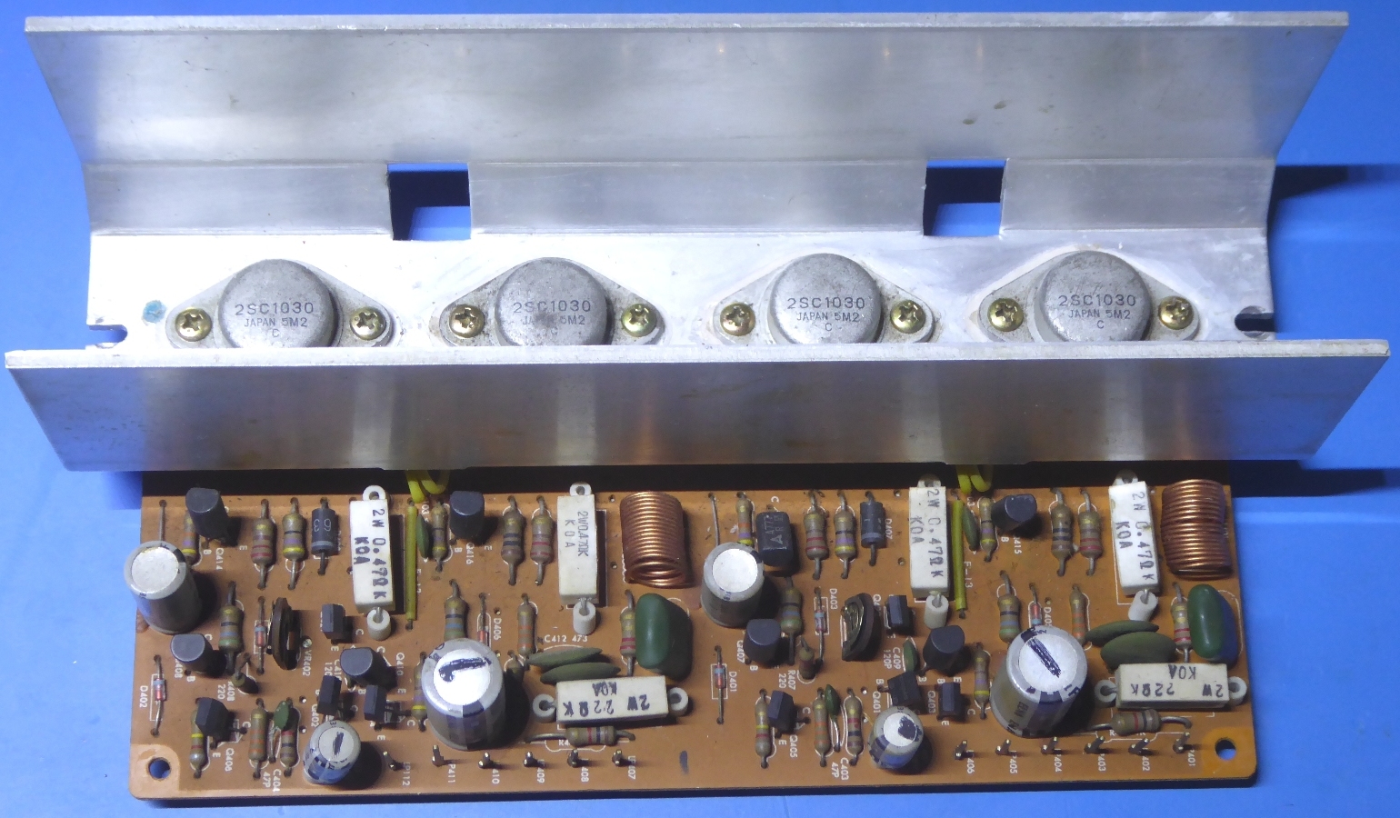
Apart from the wirewound ones, all resistors are metal film. The bias trimming potentiometers are multiturn ones.
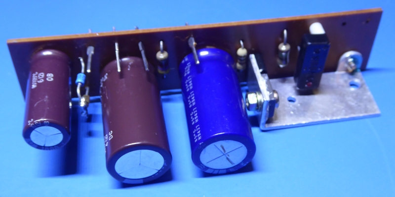
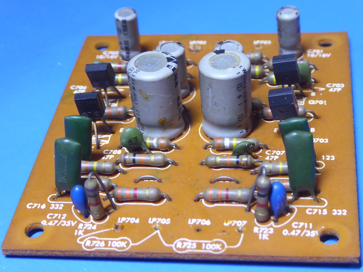
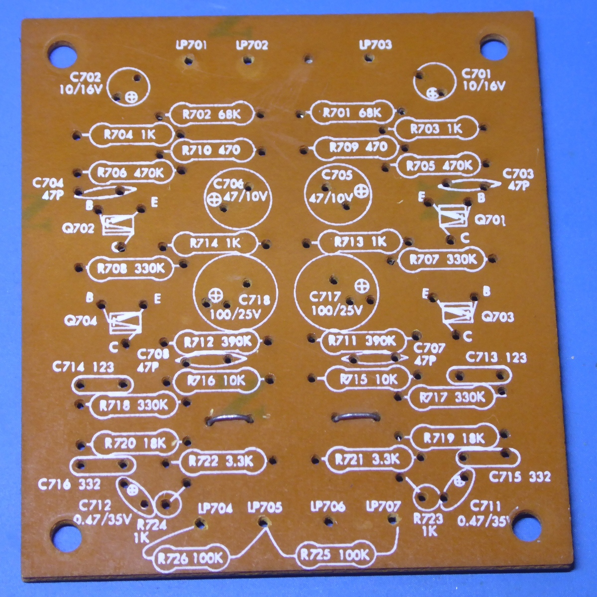
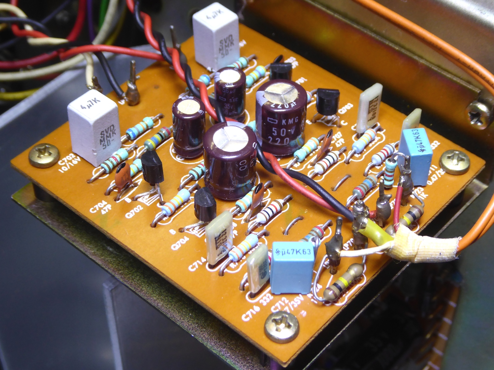
RIAA input circuit card.
This card was easily taken off, it did get new electronic parts.
Also this one did have small Hitachi transistors (2SC1344), known to be causing troubles like noise and intermitting deterioration.
Although: All removed transistors were tested, but no defective ones were found.
Observe the nice painted nomenclature on the empty circuit card, including part value as well as parts list numbering, it makes replacement of parts easier and quicker.
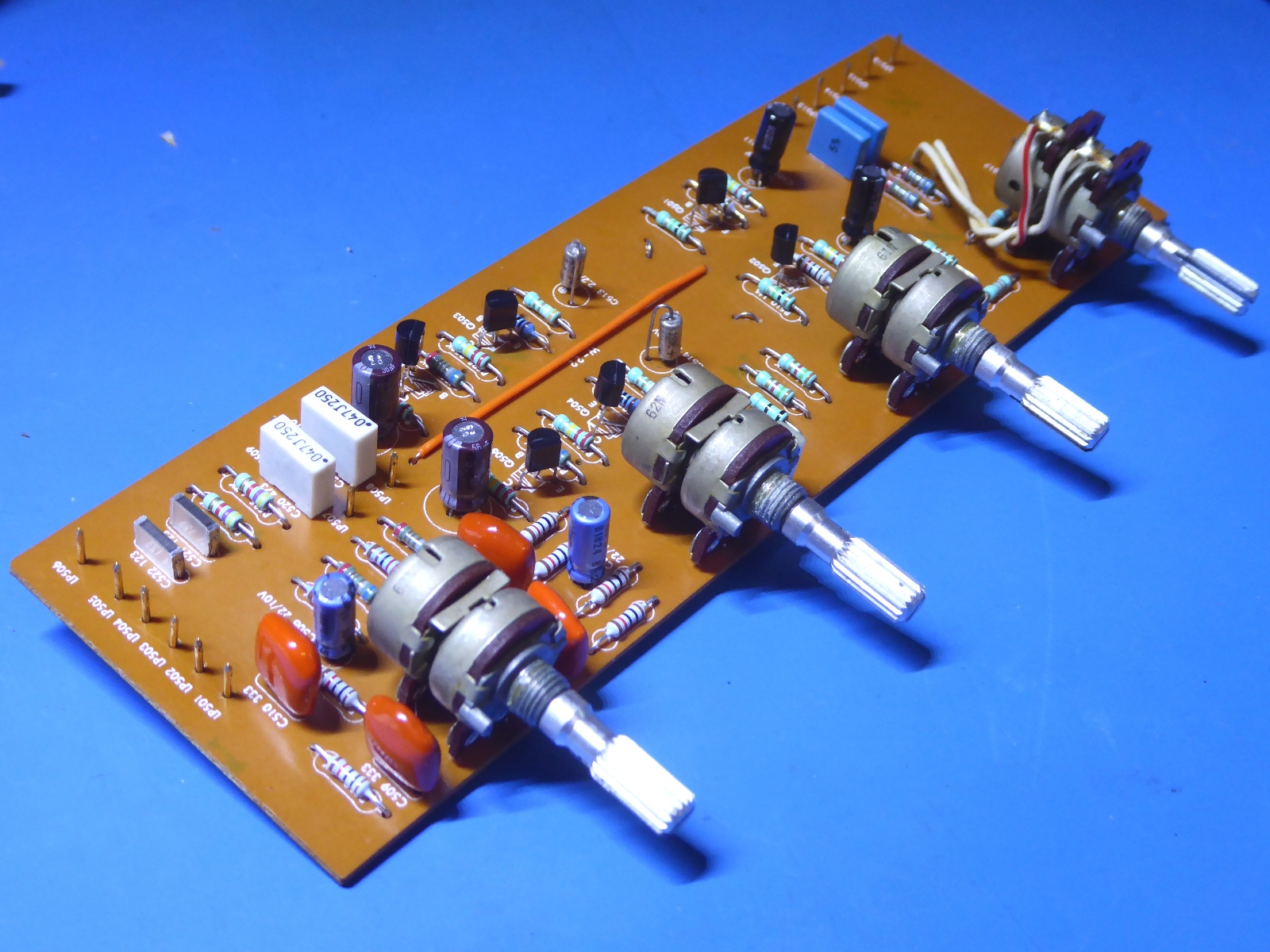
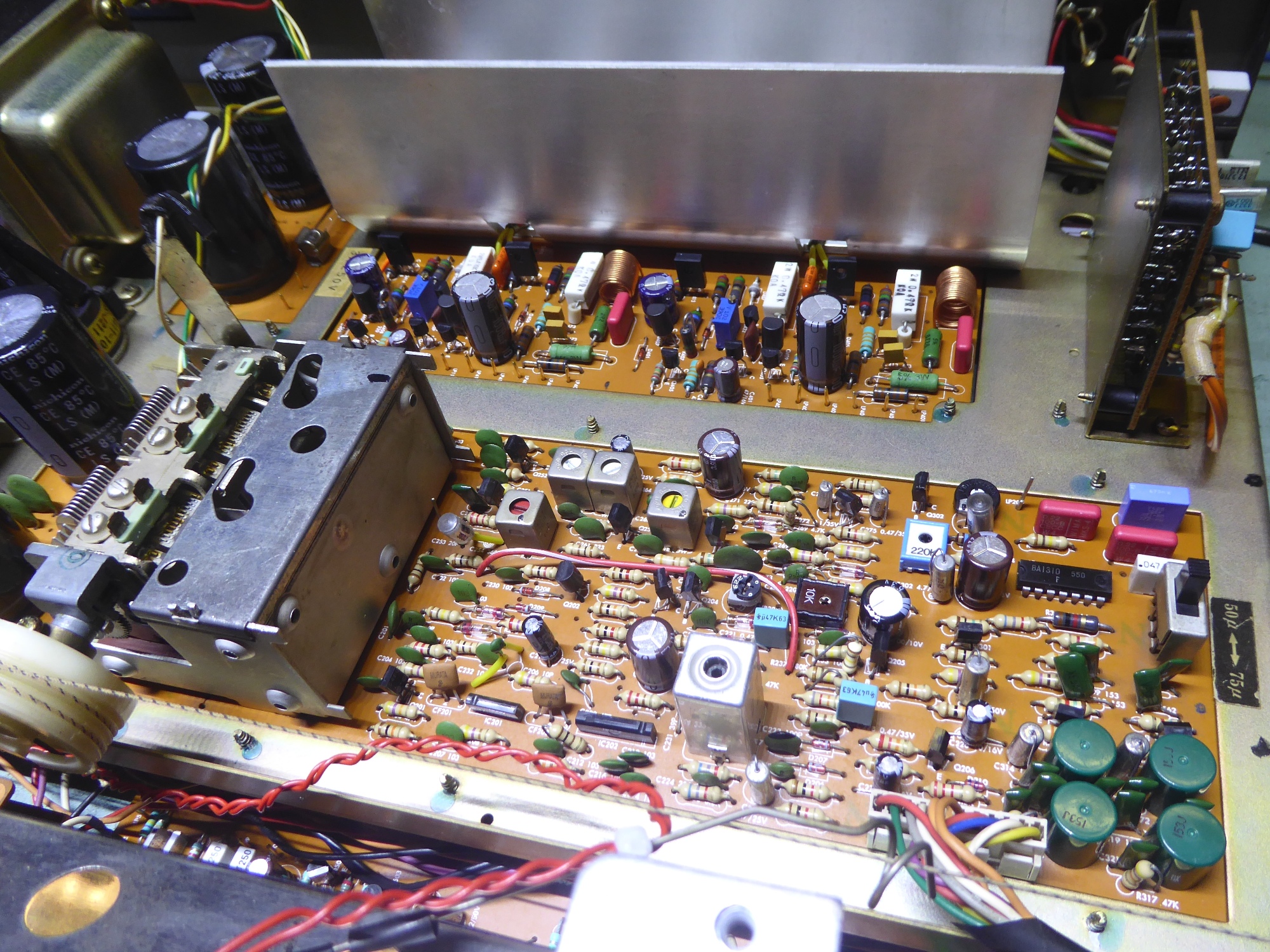
Tone control / pre amplifier.
This card had components renewed. When replacing resistors, low noise metal film ones are used.
Most little green ones are the SFR25 type.
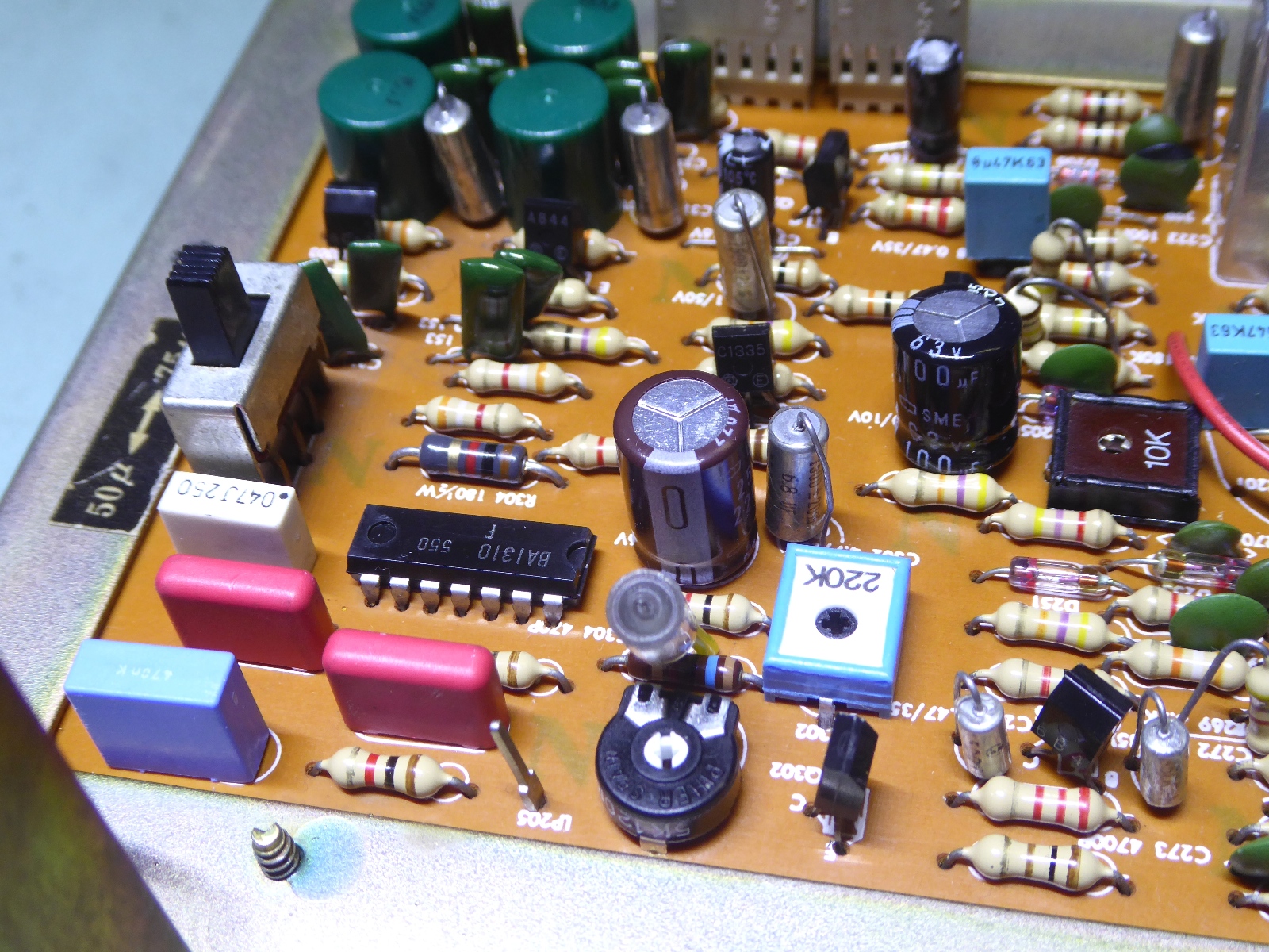
The Tuner board.
Trimming potentiometers and electrolytic capacitors were replaced, and also a few film caps, jsut because they were big and ugly, having enough new parts at hand.
Some of the Tantalum capacitors were replaced by metal-case Sprague 150D and alike capacitors. They are NOS and can be used, because they do not age. You do not want to buy those new, as their cost is 5 euros or more, each...
The R304 180 Ohms resistor supplying the stereo lamp, was replaced by a 1k one, as it supplies a LED, now.
To retain the pink-red look of the "stereo" indicator, a warm white LED was used, instead of a red one.
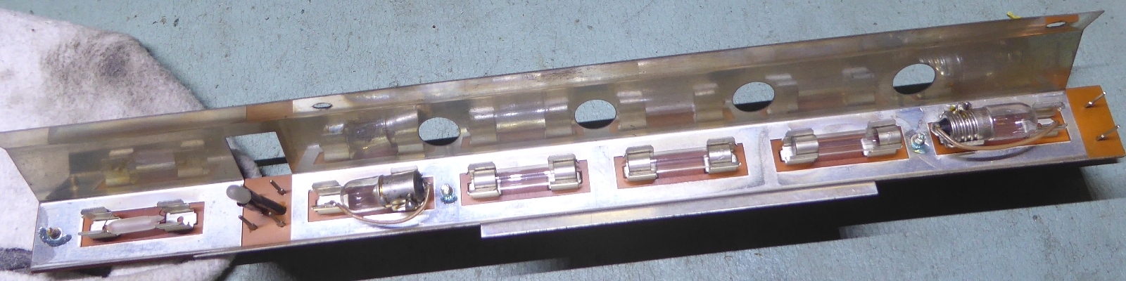
The receiver backlighting.
The old lighting was partly defective.
Apparently, a previous tech worked on it, putting in another type of lamp. I did check: Lamps of the proper size/voltage/current combination seem simply obsolete and unavailable....
The wiring of the transformer NOT supplying the preamp is used, and a power supply circuit card was made for the 12V LED supply.
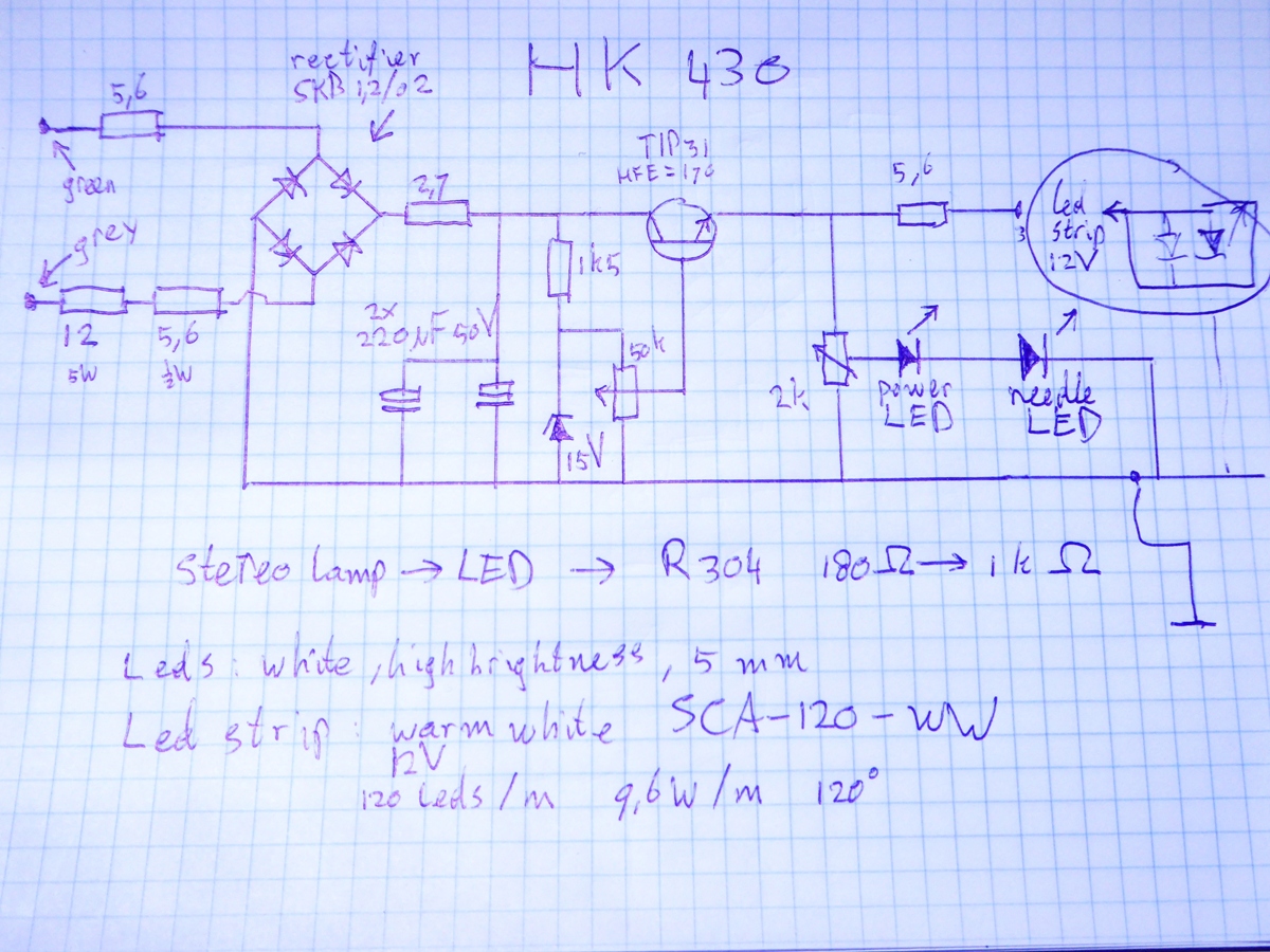
The schematic below is the LED string power supply. The 50 k potentiometer sets the string voltage to around 10 Volts, which is sufficient for the backlighting. From the regulator transistor a second potentiometer taps the voltage, supplying the two other LED's.
As noted in the power supply section, the power is derived from a special circuit, made for this.
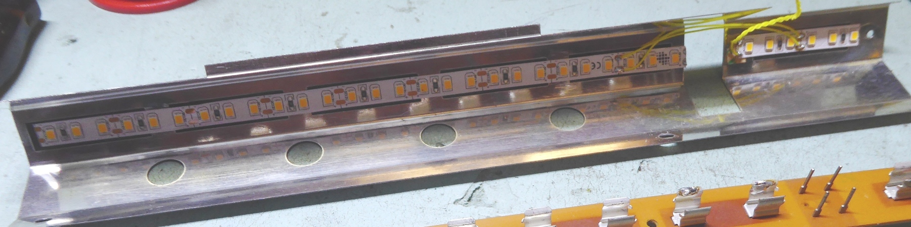
A new LED string was mounted on the backlight reflector. The tuning needle exploits a SMD led now, it is in series with the Power button indicator, which is a high brightness led also.
An additional trimming potentiometer is used to regulate the lighting of the tuning needle and power button.
The power supply board. The transistor employs two ceramic washers and a metal piece, together, as a compact heatsink.
There also is an off-board 12 Ohms resistor on the back of the big smoothing capacitors circuit card, connecting to the grey transformer wire.
I did choose to mount a connector on the little board.
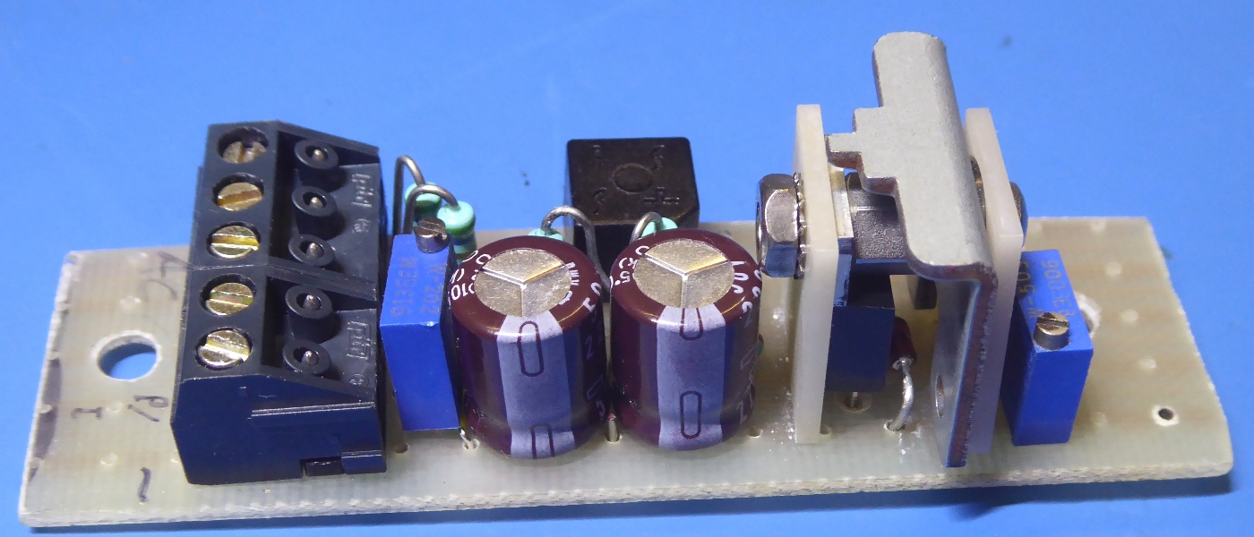
The new LED string can be cut each few centimeters. It has an adhesive strip at the back. The part number is SCA-120-WW.
![]()
Some pictures of the receiver.
Ga naar Gerards page / go to Gerards page ---->>> ![]()