Ga naar Gerards page / go to Gerards other pages ---->>> ![]()

Restoration / recap / refurbishment of a hitachi ia-1000 amplifier.
This very nice IA1000 was sold in 2025.
![]() Gemakshalve is deze pagina alleen in het Engels geschreven.
Gemakshalve is deze pagina alleen in het Engels geschreven.
![]() This page was written using English language only.
This page was written using English language only.
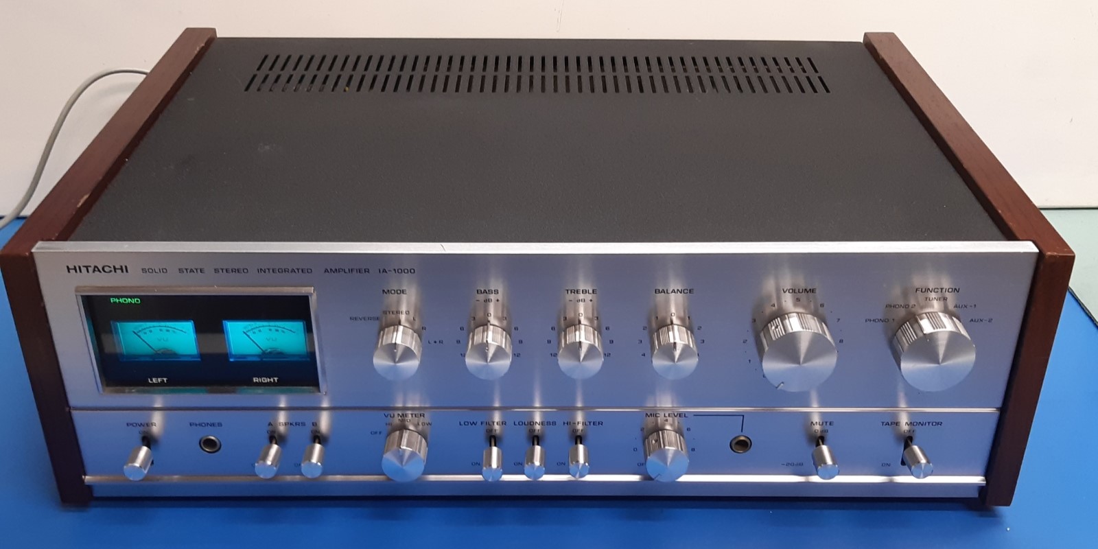
Hitachi IA-1000, refurbished November, 2024 .
This Hitachi was bought from a marketplace trader in the Netherlands, it was stated in the advertisement it produced hiss and in need of attention. Therefore apparently it was not popular and I could buy it for a reasonable price (at least, reasonable for people confident able to fix it.)
Opening it up, it looked quite clean. Powering up, it indeed was noisy, everything was functional, with the exception of the microphone input.
Although advertised as a 2x55 Watt amplifier by its service manual and on the hifiengine site, the wattage is actually according the Hitachi brochure calling for 2 x 45 Watts RMS.
In the end, undistorted power proves around these 45 Watts (continuously). The figure also depends on the mains voltage (226 when testing) and the transformer tap selection on the back of the amplifier (220 or 240).
Obviously, it had some kind of rebuild before, using quality components, but ignoring or being unaware of some transistor specs risks.
It looked the power switch ever was replaced, potentiometers and switches were sprayed with cleaning fluid. (fortunately: not too much!)
This could have been decades ago. More recent were LED fuse-type style lamps in the power indicator meters.
The main first objective was considered the noise, which was very apparent and audible, most suspect was the the preamplifier card.
I started the rebuild November 2024. Note: the rebuild is a hobby, not every step was a necessity, and the goal is to have an amplifier which you simply can use without considering lack of quality versus modern good equipment, audible hiss during listening music would be a no-go.
To be able to follow the technical story, one will need the schematics/service manual, to be found at elektrotanya or other internet source.

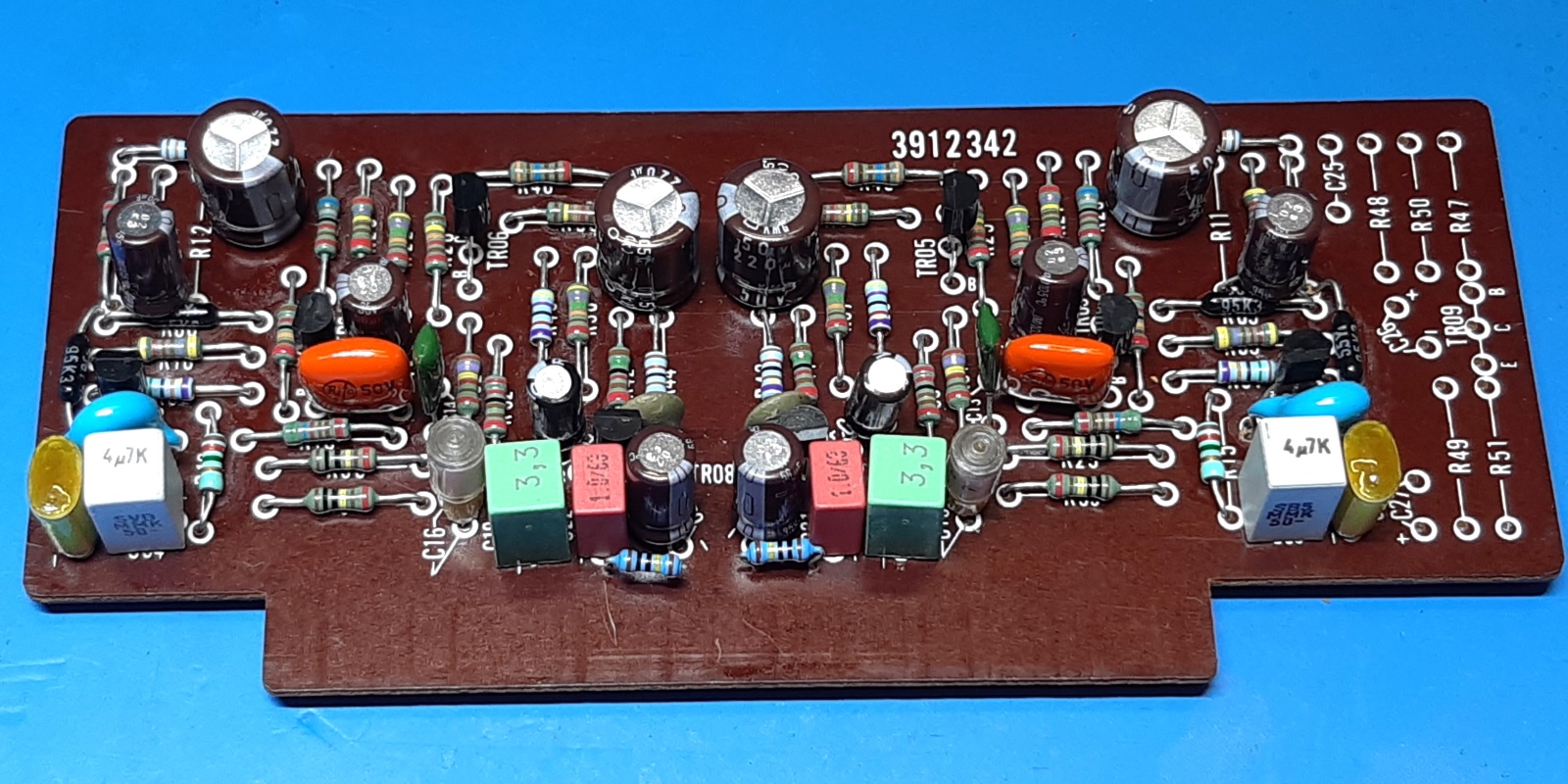
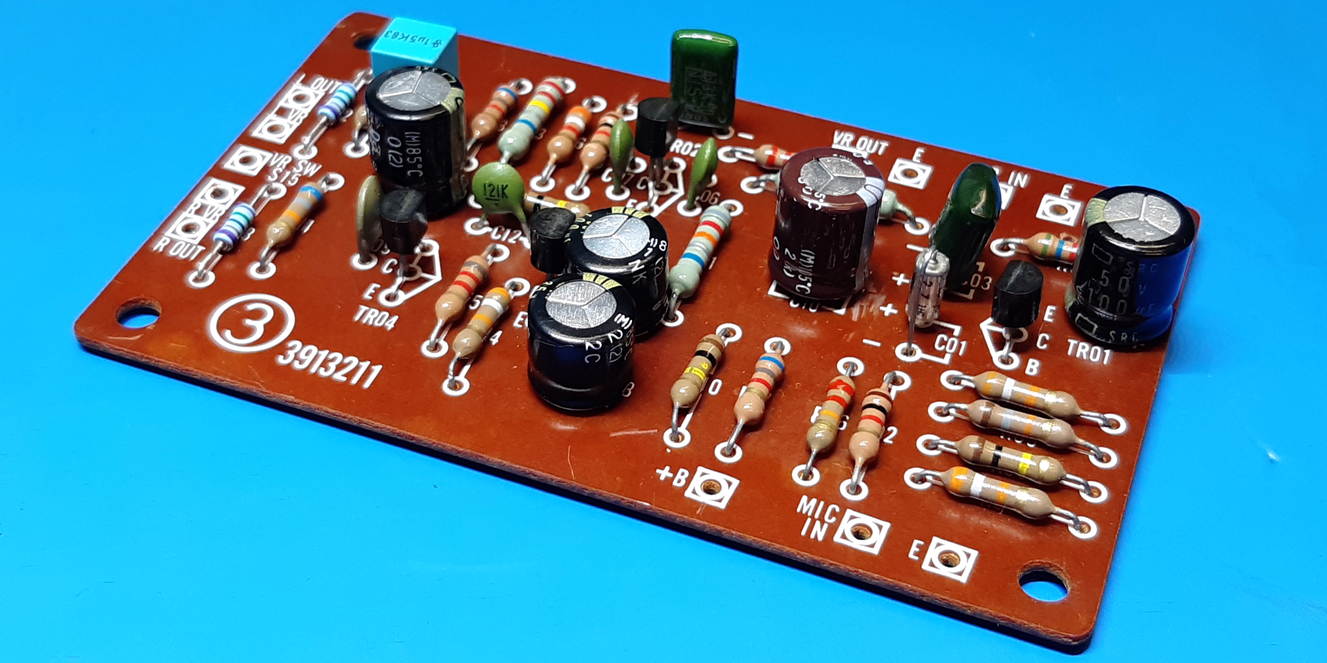
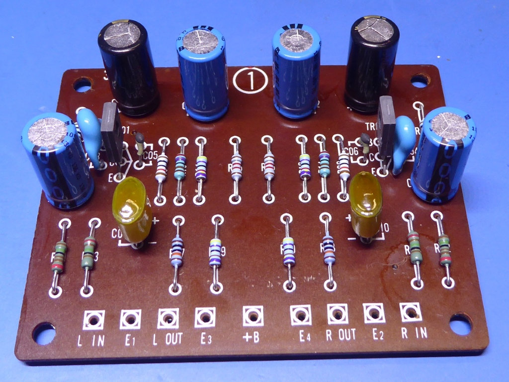
The pre-amplifier circuit card.
As this card was the most suspect for the hiss, it was the first to be refurbished.
The schematic calls for the known noisy 2SC458. Apparently, they were replaced by BSY80 transistors, these are European types and very ancient. Apparently, they were not any better than noisy 2SC458 ones, maybe they are much worse...
One or more of these transistors could be driven beyond their VCE specification of 18 Volts, so I think this change was not for the better.
I presume, this replacement was done many years ago.
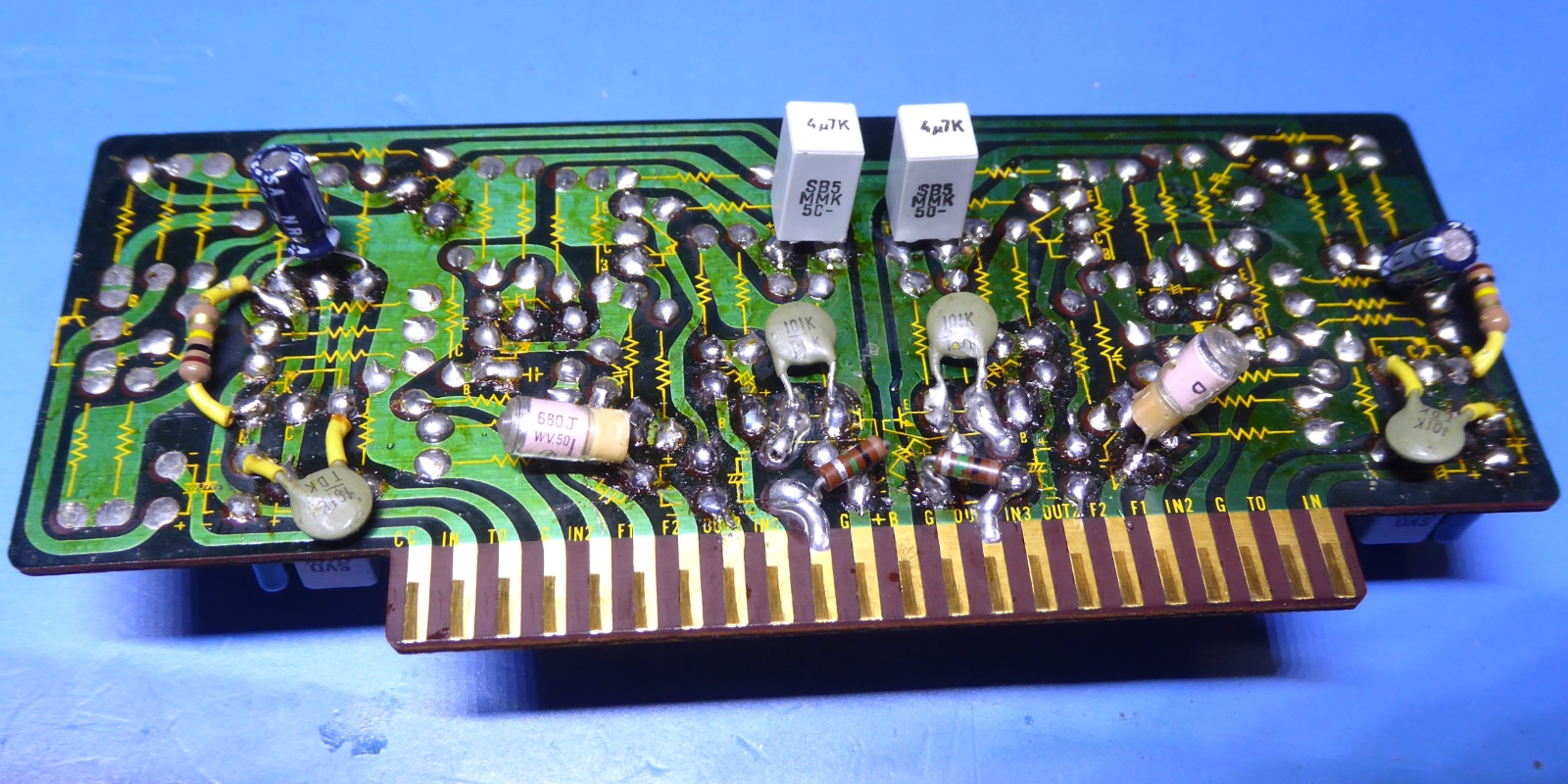
A lot of components were mounted on the solder side of the card.
I can not think of any valid reason to regulate the volume before it enters the preamp, as it affects signal to noise ratio a lot at low volume, but Hitachi apparently did....a not-so-smart approach from the sixties/early seventies some did.
As the pictures indicate, this amplifier card was "tinkered before". Partly, high quality film capacitors were used, so I simply re-use these where they fit the card.
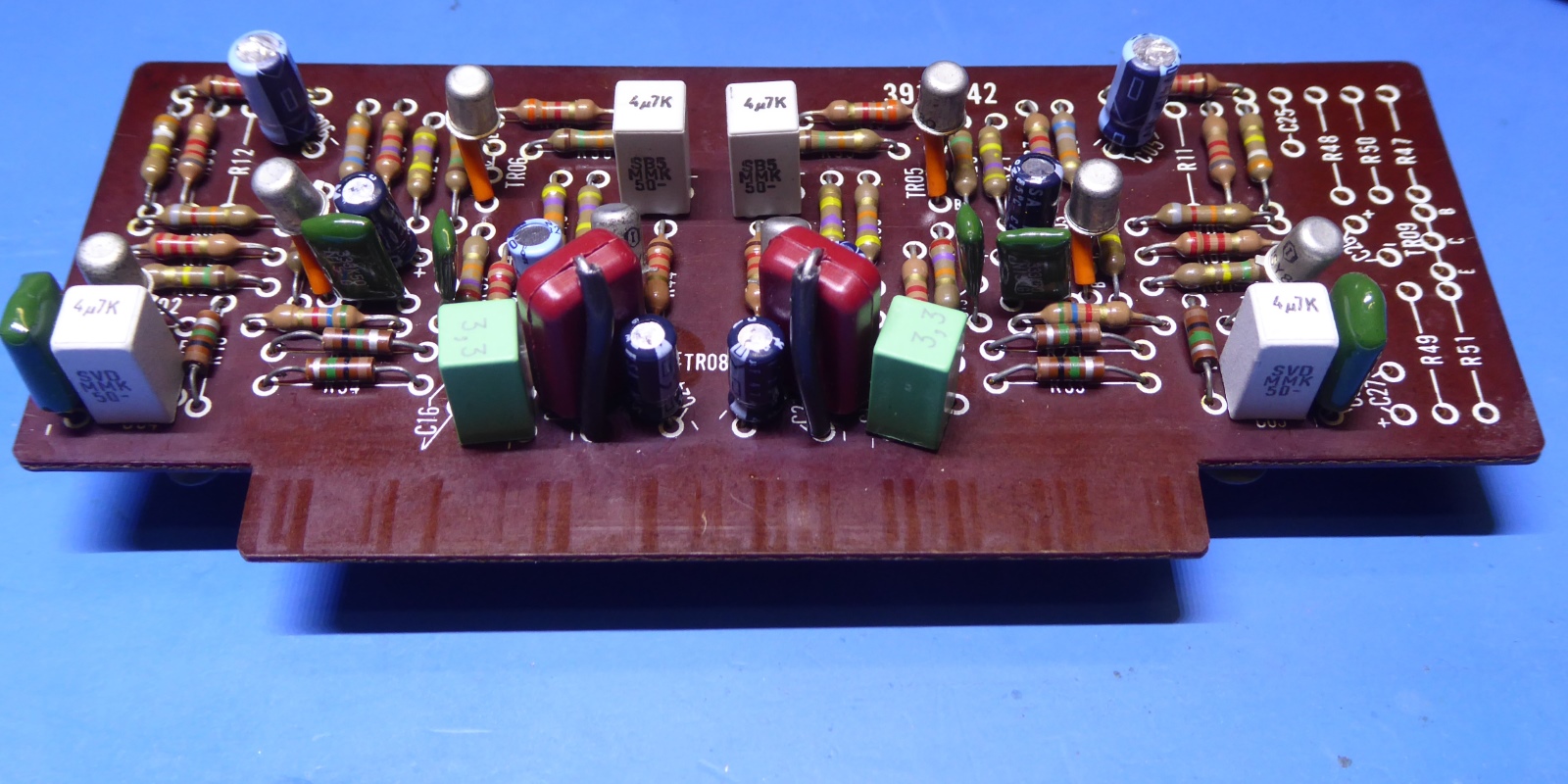
The emitter-follower transistors TR05,TR06 were exchanged for KSC945, the others are KSC1845, now.
The first stage did amplify the signal almost four times. I adapted the resistor values to make it about 1.5 times, making it less sensitive, to create a better signal-to-noise ratio.
R07/R08 are 4k22 instead of 8k2, R9/R10 are 3k16 instead of 2k2, R03/R04 are 270k instead of 390k.
Drilling additional holes and adapting values, the board was adapted to carry all components at the components side, making it look more neat.
Components choices are based on availability, assumed suitability for values, and physical size.
All resistors are high quality low-noise metal film types, now. When putting the amplifier back in operation, the noise was gone, so this made the amp worthy to put in more time to refurbish.
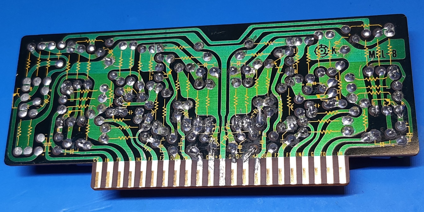
A noteworthy thing is the circuitcards themselves (solder tracks) are of quite good quality, above average compared to most amplifiers I refurbished.
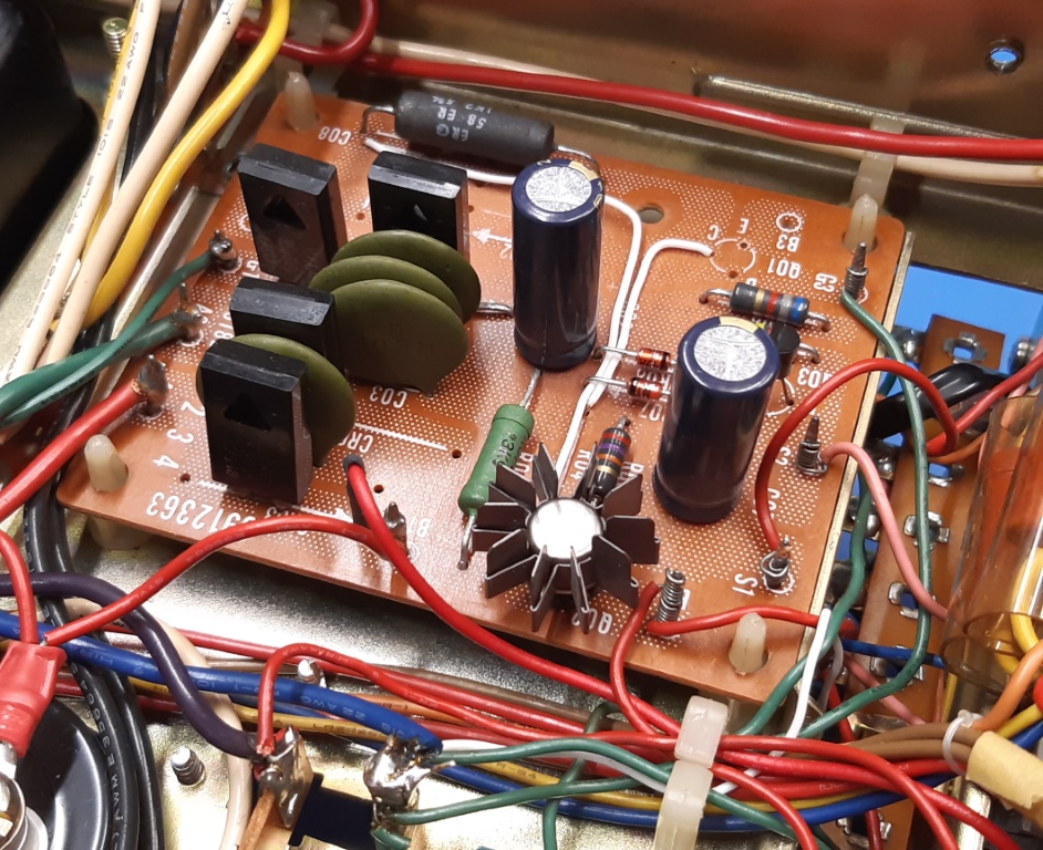
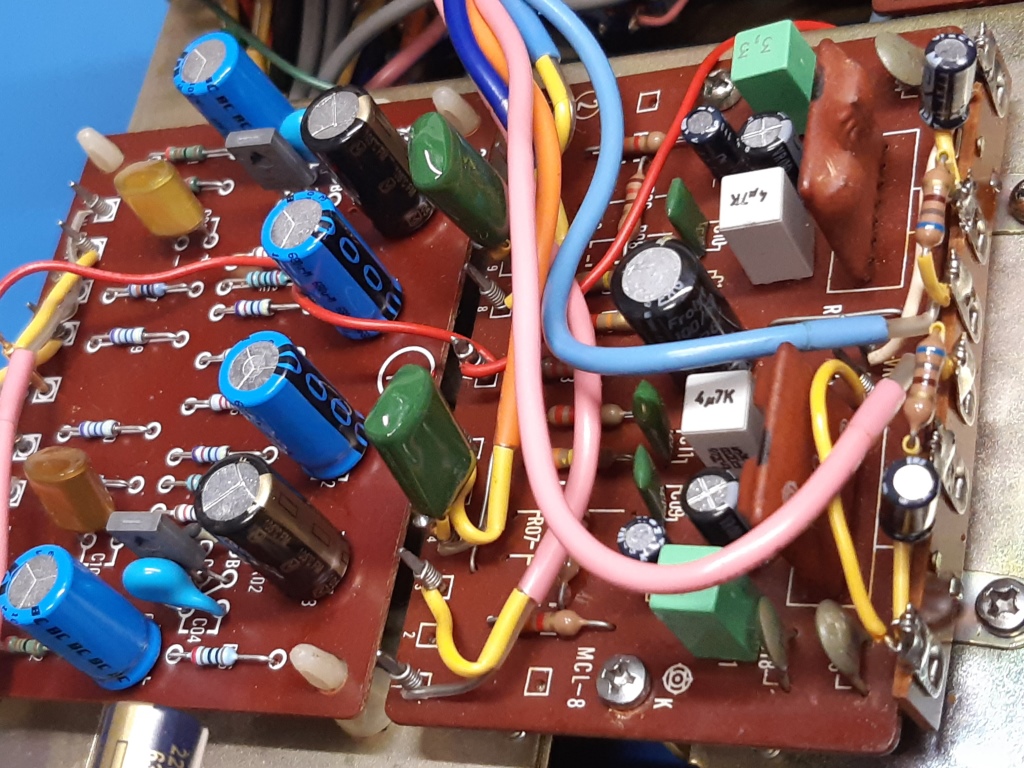
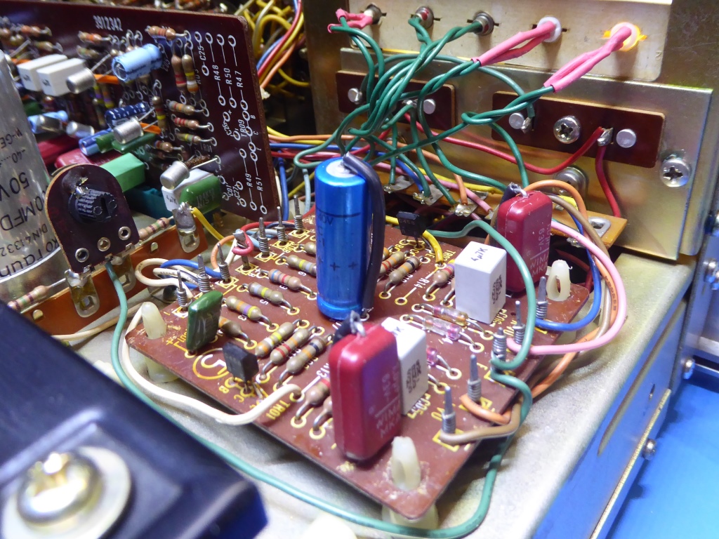
The power supply and its associated circuit card.
This amplifier has a 2200 microfarad capacitor specified for power smoothing, it proves to deliver some 72 Volts (probably 75 if mains voltage is the very same as the value of the mains voltage selector on the back of the amplifier).
In the past, this was modified to TWO 10000 uF / 50 V capacitors in series, making 5000 because of having them in series. Having a Kemet ALC70 6800 uF /100V screw terminal type one available, this is what I did put in.
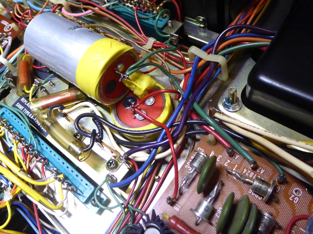
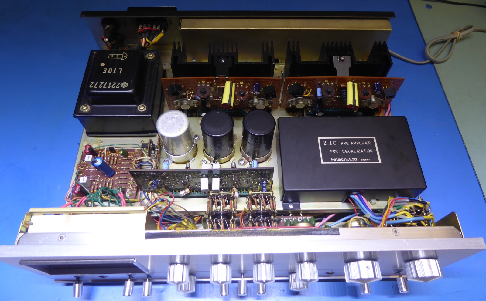
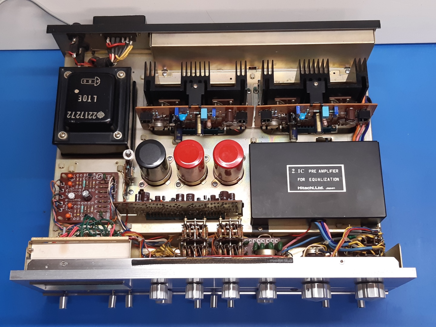
The two pictures just below here show the situation as it was encountered. Of course, I want to get rid of the horizontally mounted capacitor.
Although it worked fine, it is simply not how I like it.
BTW, having two smoothing capacitors in series is not a smart idea if done without balancing the voltage using resistors to cater for capacitor leak differences, as was the case here.
However, I measured the voltage over them and while the difference was less than 2 Volts, it proved to be no problem in this case, leaving a big margin compared to the 50 Volts capacitor rating.
Old situation:
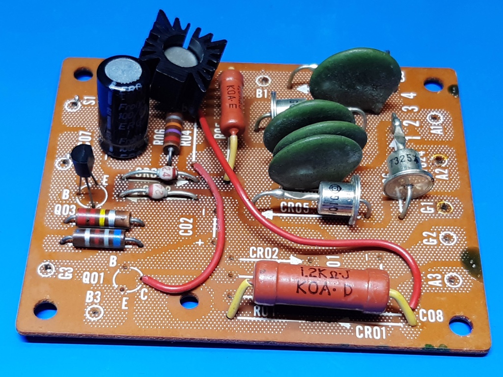
Assuming the rectifier diodes were hardly up to the task, it was decided to use more sturdy BYX71-350 ones, as I have a lot of those. Those are 7 Amps fast/soft recovery diodes made by Philips.
No real data is not to be found on the internet considering the original diodes, but the size of them suggests they will be around 2 Amps at the maximum or maybe less.
I added a 220 uF capacitor for migitating Zener diode noise, I replaced the zeners themselves because of a brown pcb spot (they went hot), and changed their feeding resistor from 1k8 to 3k9 to lower their dissipation.
Apparently the transistors were already replaced, before. TR03 is a BC327, and TR02 appeared to be a BC340-16.
At the moment of power-up, the voltage will exceed the maximum VCE specification of the BC340, theoretically it was not suitable/on the edge, so I did exchange it for a 2N3440 tested for sufficient HFE.
The old heatsink of it was a little loose and therefore it was replaced, also.
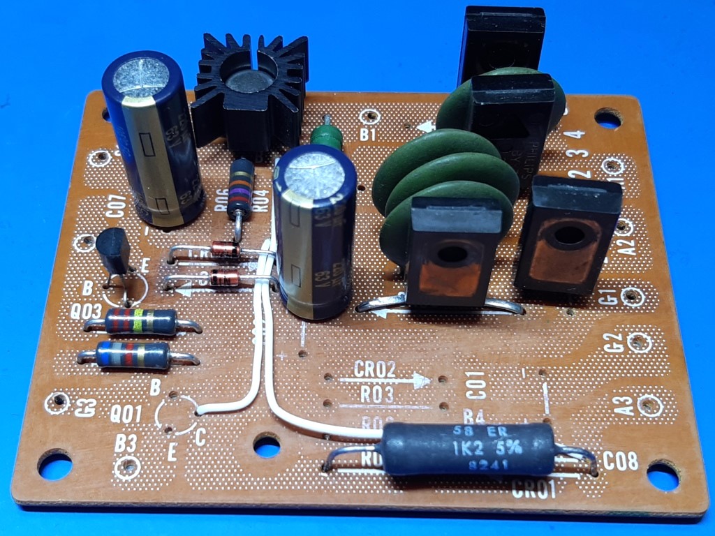
New situation:
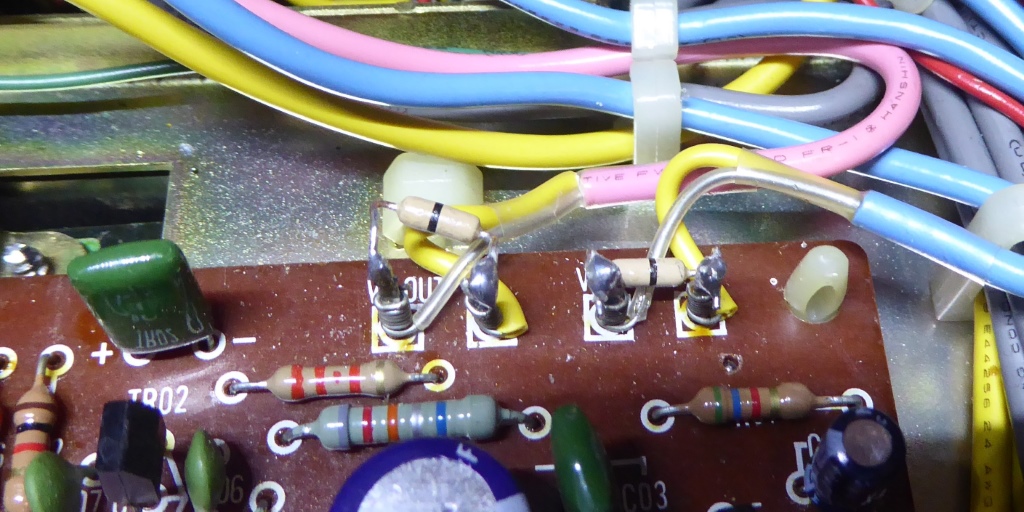
The Microphone preamplifier card.
This amplifier, located on the bottom side of the amplifier, appeared to have its input and output shorted, so it did not work.
One could be lured by the less-known "zero-ohm resistors", deliberately wired over the connections, on the left picture.
Probably, this was an attempt to migitate the noisyness of the amplifier....(or to prevent people abusing the amplifier during loud karaoke parties......)
I replaced electrolytic capacitors, trying to use pcb hole distance fitting them, if upping capacitance would not hurt performance. I did NOT replace any resistors, assuming a microphone environment in the house is noisy by itself and resistors changes would not help that much.
Still, I decided to replace the 2SC458 transistors, as they often fail. 2SC1815Y ones are used, instead.
As the normal preamplifier signal is routed over this card to merge with the mic output, and wanting to have the microphone signal having less influence as well as lower normal preamp noise, I assumed lowering the R22 and R23 resistors from 15k to 7.5k appropriate. Microphone volume appeared OK after testing with the JBL dynamic mike I have.
Interesting is the fact when the mic preamp is switched off, the switch shorts its output by switch S13-2, potentially damaging the output transistor if "all components were ideal".
This, because the transistor shorts its 220 microfarad smoothing capacitor. Only because of the base current is limited by the 39k resistor this shorting current is limited because of HFE limitation of the transistor keeping current within maximum specified. The 2SC1815 does not have higher HFE than the 2SC458 coming out, its max current spec is a little higher. Sometimes, one simply finds design flaws....
On the right is the picture after component replacement:
The Moving coil preamplifier card.
This "pre-pre" amp was repopulated, I used a medium power TO-126 transistor BD329. It has good HFE and high frequency specs and its low "base resistance" caters for low noise.
Consulting the internet, it seems for ultimate low noise in such common base amplifier, a low ESR capacitor between transistor base and ground seems essential, so I did put in a 1000 microfarad Panasonic FM.
Anyway, switching to MC versus MM having nothing connected on the input, does not make the noise higher, when putting volume at maximum, a good sign. Having no Moving Coil cartride, I can test only using a microphone, instead.
The Equalizer preamplifier card.
This card was recapped already, and besides replacing a few resistors for low noise metal film ones, there is nothing more to be done, however:
It employs a so-called "IC" FA-6001T, which probably is a ceramic substrate using thick film resistors (which may be noisy), and clearly visible it has normal transistors mounted on it.
One could regard it not really an IC.
If I keep the amp MAYBE I will replace those by veroboard circuits using discrete components one day, but hiss is very low using the turntable.
The schematic of the "IC" including resistor values was copied from the internet, so it is easy to replicate the circuit, and I am sure the schematic does not get lost.
The picture shows this card, next to the already update MC-amp card. The metal shield, not on this picture, is not that high and it was taken into account when selecting the new capacitors.
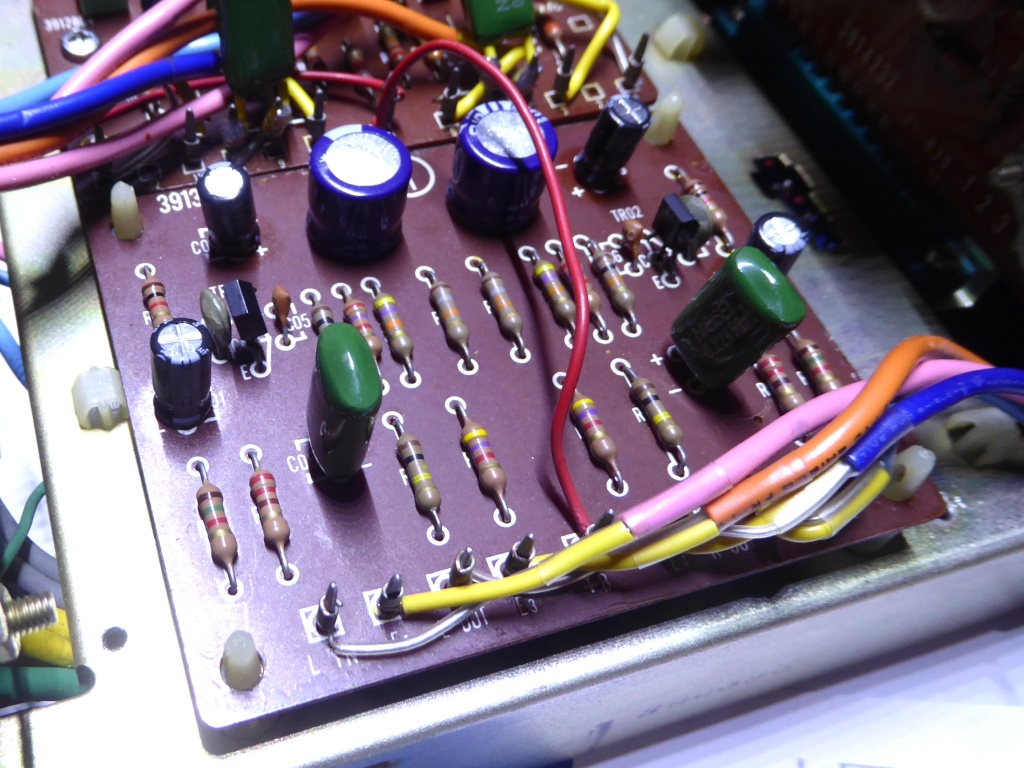
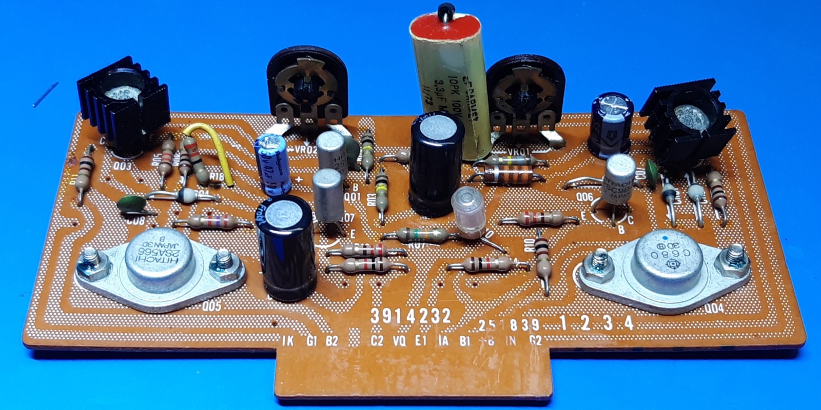
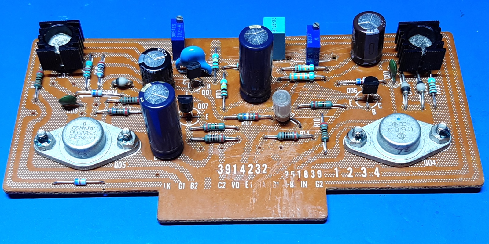
The main amplifier cards.
The main amplifiers both did work. I decided to do a clean-up, so I did partly rebuild them.
The input transistors are modern KSA992Y, now.
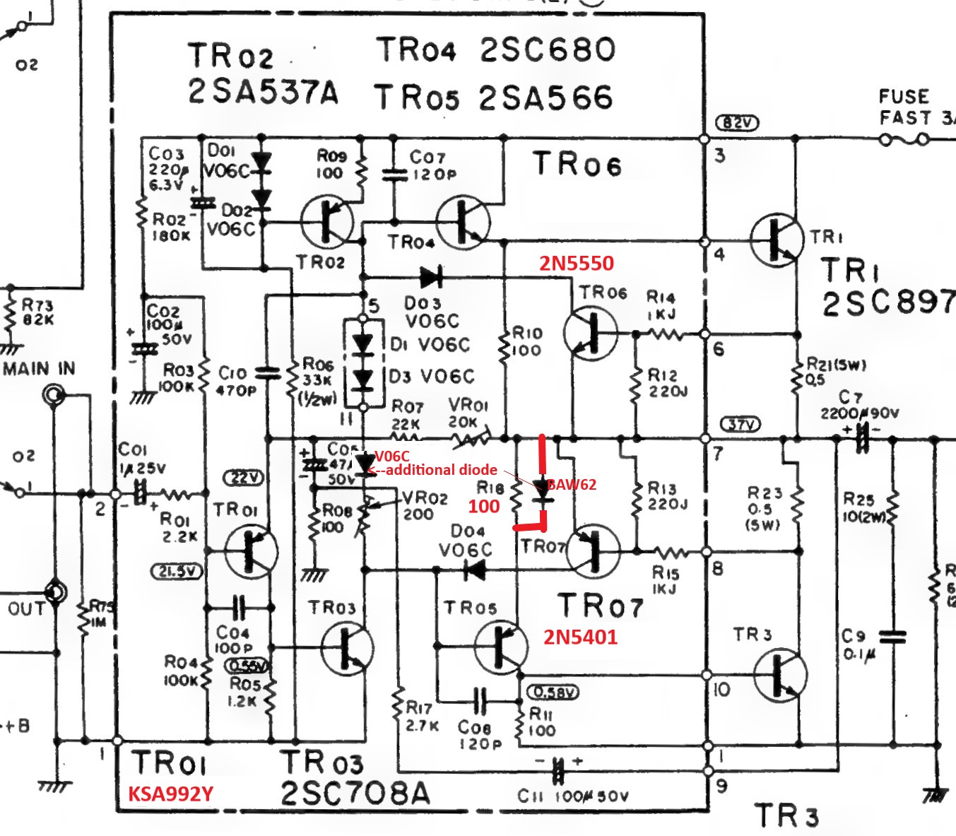
I wanted to make the "Baxandall modification" which is supposed to be always lowering the distortion in this kind of circuits.
Therefore, I added one diode across R18 and I changed R18 from 22 to 100 Ohms.
All electrolytic capacitor values are roughly doubled for capacitance.
This amplifier has output capacitors, specified at 2200 Microfarad. I found Elna 6800 Microfarad 35 V ones in there, they were very old but maybe still newer than what was in, originally. I put in high quality screw-terminal Itelcond red 4700 Microfarad 63V ones, they measured better than the very old ones.
Both cards had the trimming resistors replaced. Although the manual calls for setting the output voltage to "half" supply voltage (read: to 37 Volts), when "cranking up"the amplifier, it shows it should be lower. This is accomplished using the distortion meter, and tweak for the highest power setting while distortion is still low.
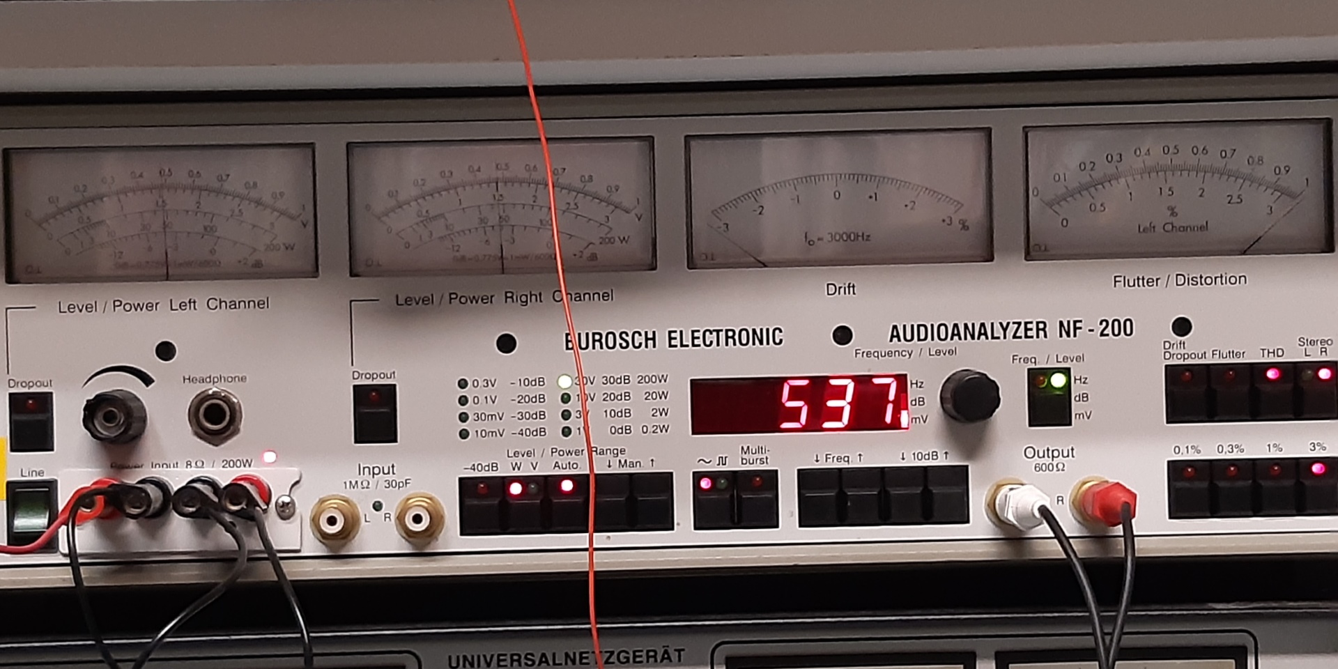
Distortion from AUX input shows well below 0.1% before the amplifier runs out of juice at around 40 Watts. At around 45 Watts distortion reaches 3% at 1000Hz on my analog Burosch NF200 distortion meter.
Mains voltage of around 225V versus amp setting 240 Volts to be taken into account...real wattage is a little higher than measured.
As the input signal is continuous, the bigger smoothing capacitor on the power supply will not make a difference, here, but it surely helps during music level surges.
Old situation shown on the left, the new situation is on the right:
Schematic of changes in red:
Unfortunately, I made a mistake in the schematic, I interchange the red text of the partnumbers of the two diodes changed. Of course, this is a text error, which I may correct later.
I cut the trace to mount the little BAW62, it is visible on the left lower edge of the amplifier cards. A VO6C diode moeved over to the R18 location (vertically mounted resistor using yellow wire on the old board in the middle on the left, and the now 100 Ohms R18 was moved over down a little).
One thing I usually do is replace any heat conductive paste on the power transistors. While having the amplifier operating on maximum power during testing, touching the power transistors showed no obvious temperature difference between each other nor the heatsink.
It also does not run too hot to the touch, so I just left them as is.
Noteworthy is the fact I checked all amplifier transistors for HFE beforehand, to avoid any troubleshooting, and decide whether to replace them, or not.
Initial measurements taken using the Burosch analog distortion meter, self distortion of the meter is around 0.01%. It can measure at 1 kHz only
It has internal load resistors are a little below 8 Ohms (around 7.7 IIRC). It feeds a 1 kHz signal into the amp using the AUX amp input. .
The needles on the left indicate the power which is just above 45W on the 200W scale. The 3% button used on the far right is pressed and now distortion is a full 3%, it gets lower right away when turning back power.
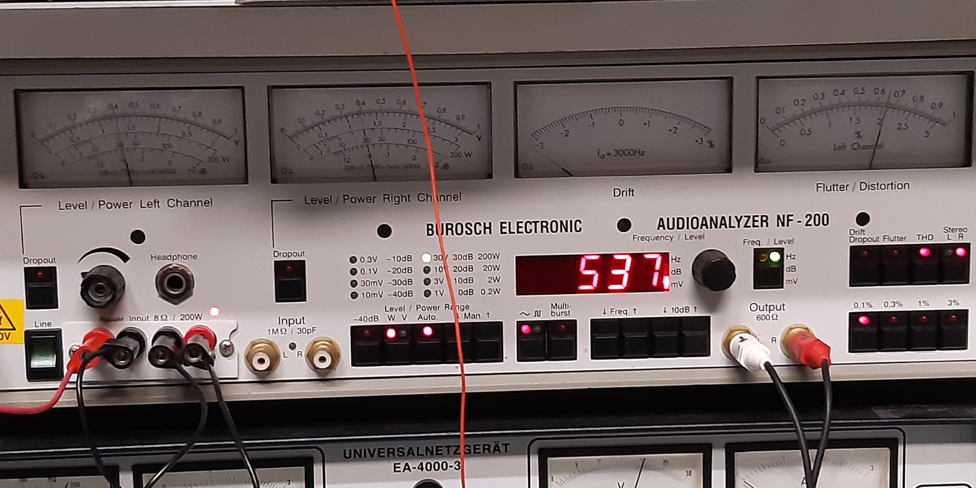
The needles on the left indicate the power which is just around 30W (40W is OK also)on the 200W scale at that very moment. The 0.1% button used on the far right is pressed and now distortion is around 0.06%, it goes slowly higher above some 40 Watts
Considering the mains power situation, a good conclusion is the amp is capable of 40 watts power at very low distortion, 2 channels driven, and goes up to 45 Watts at specified distortion.
Basically, this is a good figure for such old amp, considering this value INCLUDES the preamp, volume pots and wiring.
Manufacturers tend to show figures for the main amplifier stage only, as it makes the figures looking better....
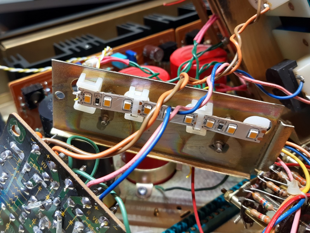
The Output meters card steering, and the lighting arrangement.
The lighting lamps exploit a separate 7 VAC widning on the transformer.
I did not like the old light dispersion on the meters, so I took the module apart. It appeared there were LED modules in. Probably they did not exist at the moment the pre-amplifier was reworked its first time!
I do not know if these look better or worse than the original lamps.
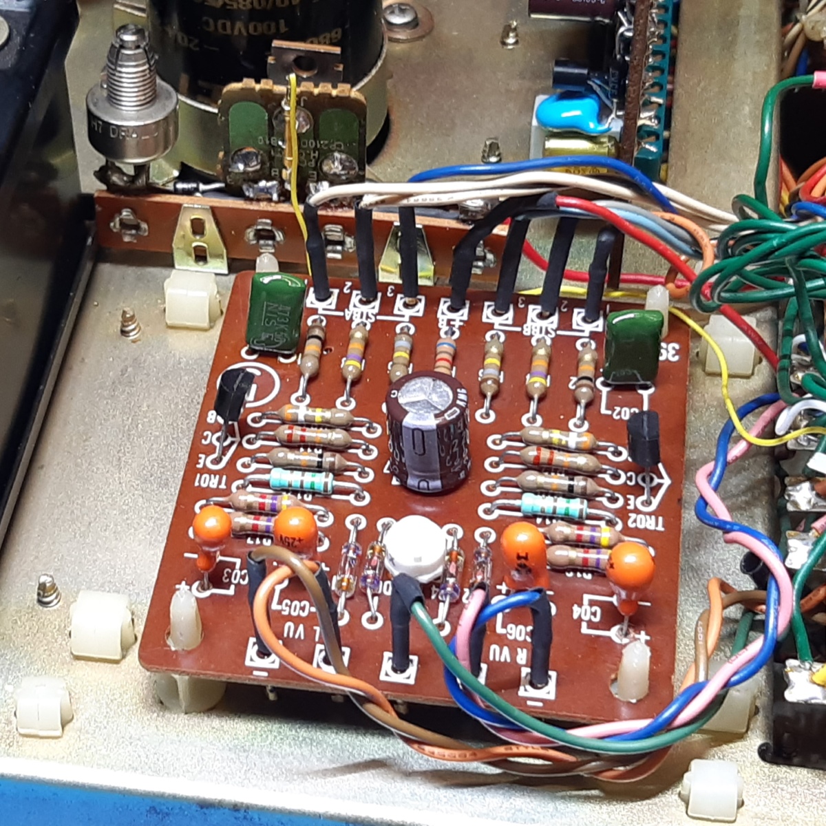
The meters are steered from a card which had a "meter balance" adjustment on a separate mounting.
Funny is the modification having "audio fidelity" in mind:two 10 uF electrolytic capacitors were exchanged for four 4.7 ones, and big 1 uF capacitors were put in.
Although appreciating an "audiophile"approach, I do not think the meters "listen to the sound", so probably that part of the recap was done by somebody not knowing what this piece of electronics is supposed to do....
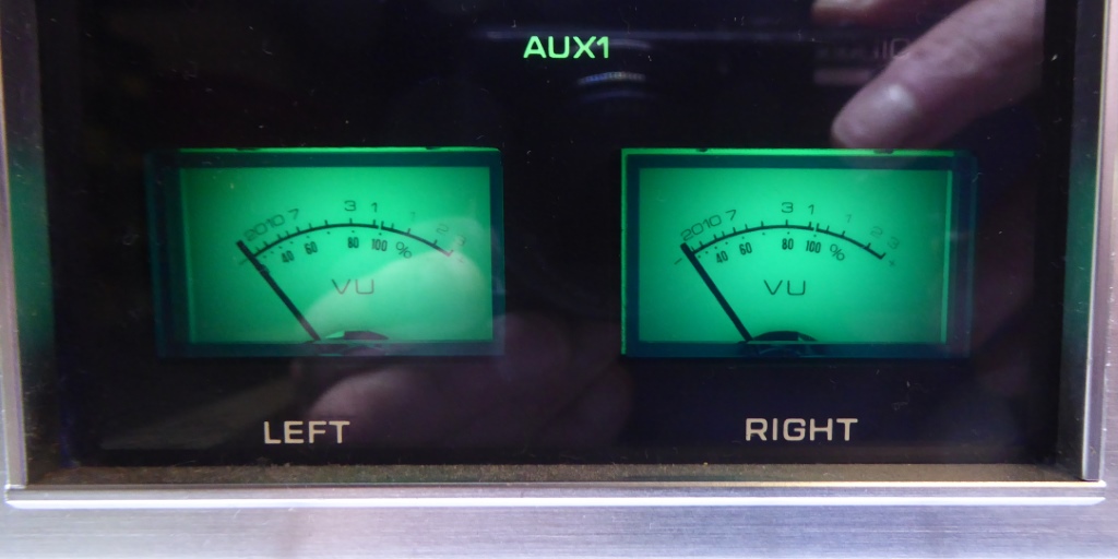
I used a 12 Volts LED strip to make the lighting look better. It is fed from a constant current source residing on the mounting strip previously used for the meter balancing.
It comprises of a few resistors, zener diodes, a TO220 PNP transistor and a metal type 2k5 trimming resistor. It is fed from the main smoothing capacitor and its current range is adjustable between some 2 and 15 Milliamps.
The meter balancing circuit was not by initial Hitachi design, as there were two resistor position already available but never used on the driver card. Apparently, Toshiba wanted to cater for different meter sensitivity compensation. A more conspicious mind could imagine they wanted the adjustment for masking possible channel output differences or meter tolerance.....
Anyway, the resistors are mounted on the card where they apparently were to be put during initial design, a very tiny trimming potentiometer is in the middle between the diodes on the driver card, now. Although, the original trimpot was already set to mid position as is the new one, so essentially it was not needed to mount, it is just to remain compatible with the design.
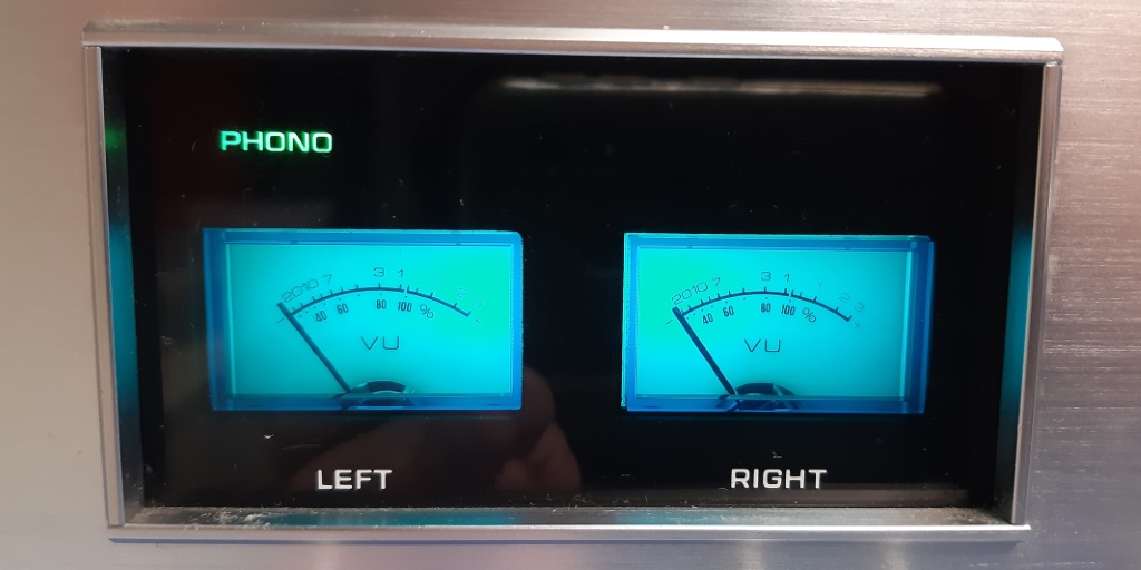
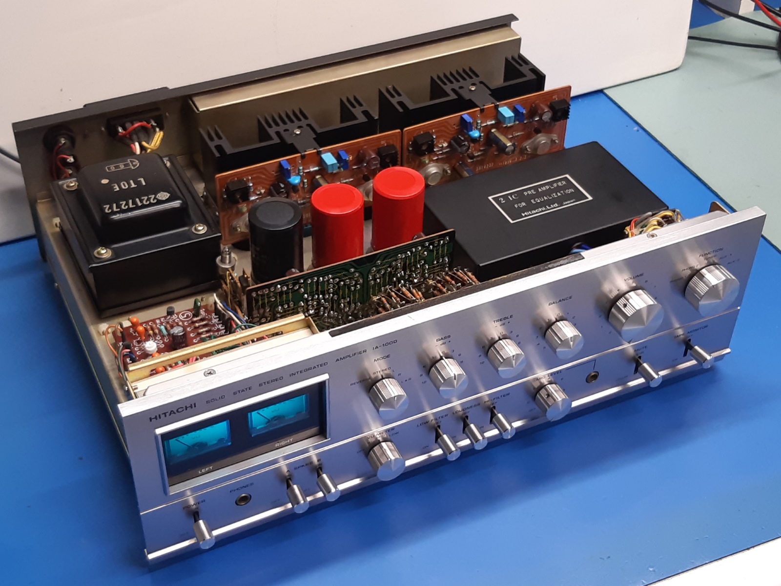
Several leisure pictures of the finished amplifier.
Top before and after.
The front
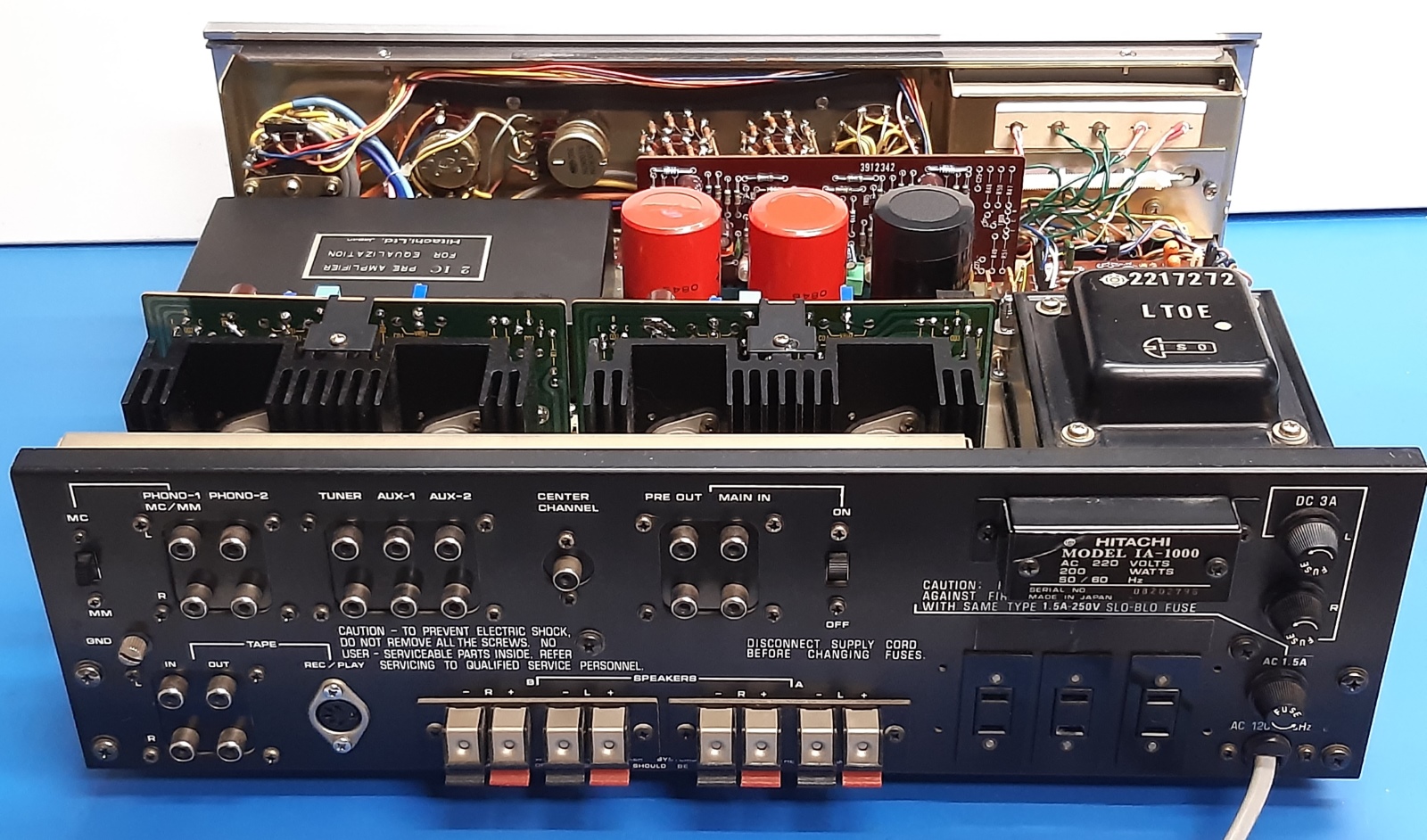
The bottom shows the snubbing capacitor over the mains power input at the most right upper section having tape wrapped around it. Checking the internet pictures, this is not done later but it is as it was originally, this is backed by a comment about it.
Observe the microphone preamp, it is located on the left.

Ga naar Gerards page / go to Gerards other pages ---->>> ![]()