Ga naar Gerards page / go to Gerards other page ---->>> ![]()
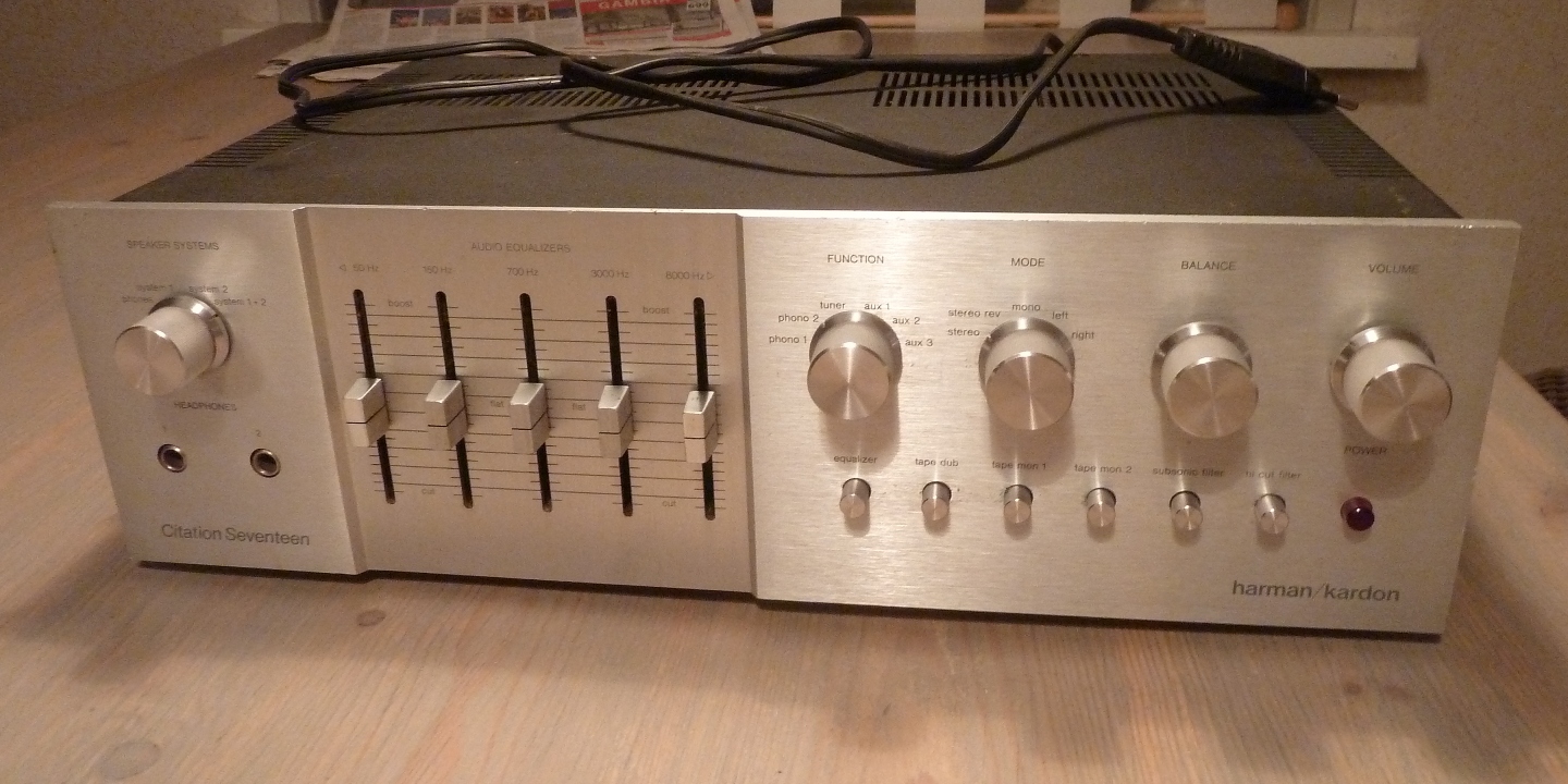
Harman Kardon Citation Seventeen restauratie / revisie / recap / refurbishment 

Deze pagina is gemakshalve verder in het Engels geschreven.
![]() This HK pre-amplifier is the more complex successor of the Citation Eleven.
This HK pre-amplifier is the more complex successor of the Citation Eleven.
According the (second) owner, it did have a restoration in the past, and at least one additional repair. He aquired it working, but one of the equalizer sliders did not work properly. After a few years, one channel failed again and I bought it.
The first time opening it up, in 2011, it was found almost half of the transistors were European types, and still several American ones (having unknown specification HK partnumbers) which were partly defective. The defective ones were replaced, some capacitors, and two defective opamps in the equalizer. Later, I found two equalizer channels out on one side, defective opamps again...
As it seems, one by one, ALL original semiconductors were going defective, there must have been severe damage in the past, maybe it suffered some peak voltage input from a lightning strike?
A "sonic experiment" challenging "audiophile boutique capacitors": Apart from three main power supply capacitors, ALL replaced electrolytics are Sprague 150D or alike NOS metal-style tantalum capacitors, 20 years old average.
Almost all new transistors are European types, preferred over the Japanese types because of the compatible pin layout for mounting.
This continued restoration is dated november 2014. Because this is a "restoration", parts are replaced to make a "nice restoration" so there is not always a specific need for replacement.

Enjoy the pictures. When old and new situation is presented, the old situation is on the left.


The inside of the amplifier
The inside of the amplifier is divided into separate areas.
On the left a compartment is used for switching of loudspeakers. To be able to do this, a special connector getting output from a main amplifier can be connected. Basically, it has nothing to do with the rest of the preamp, this also applies to the headphone connector.
The boards in the compartments are mounted using good quality connectors of a rather big size. Loosening bolts on the card edge clips, it is very easy to remove them.
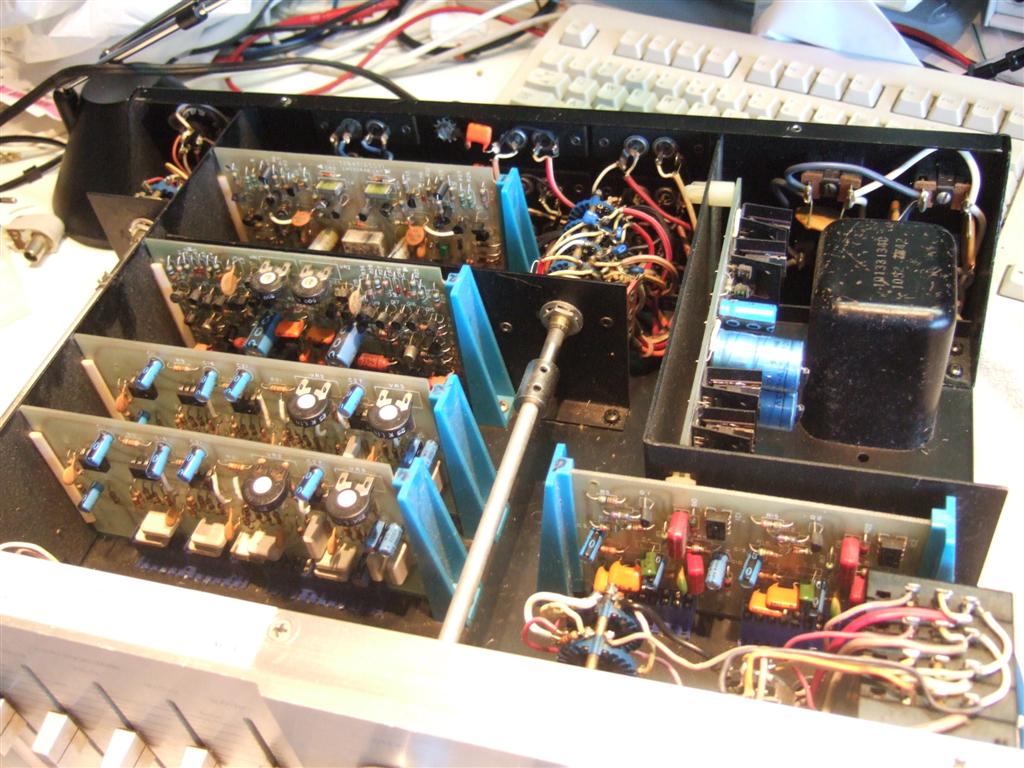

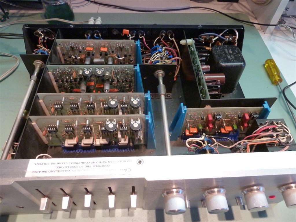


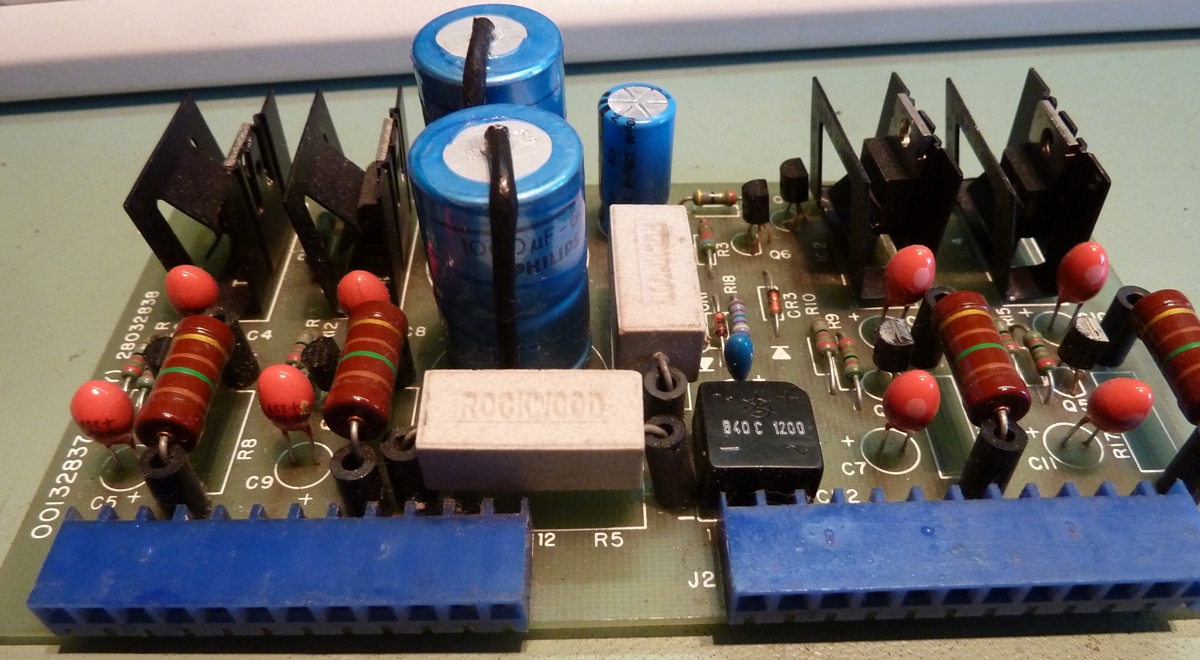
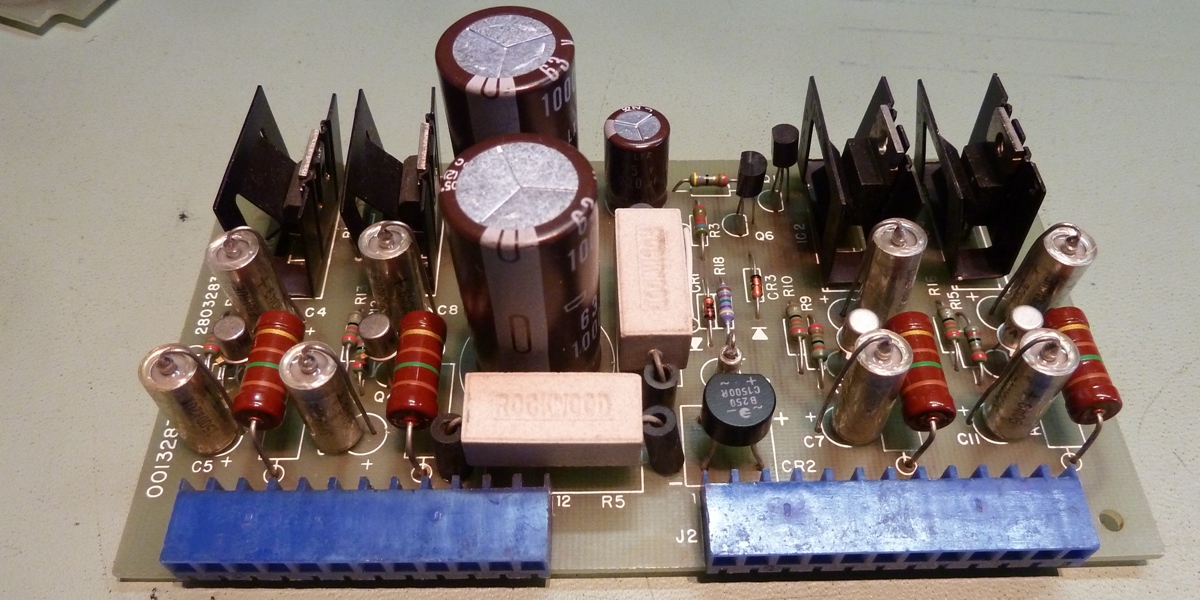
The power supply board
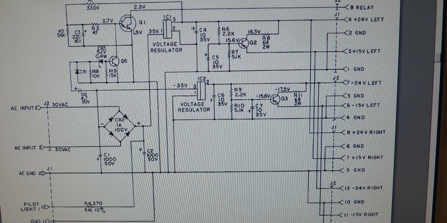
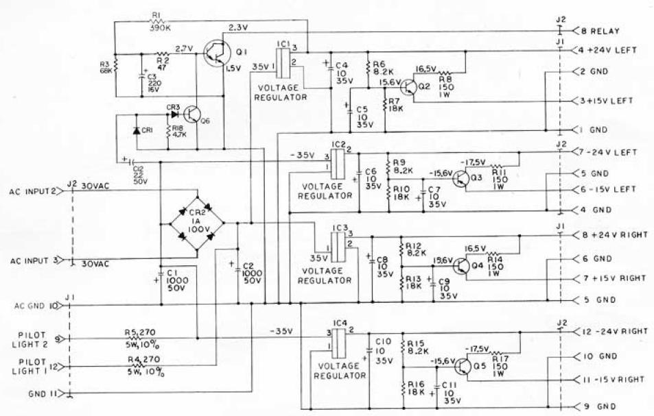
The power supply schematic which is to be found on the internet, differed from the actual power supply board inside of this pre-amplifier.
After the fix-up, a new manual was found at Elektrotanya, this one has a darlinton transistor driving the relay, while the transitor able to cut the other one off was found to be a darlington also in THIS supply board. Still a small difference remains.....
It provides +24 volts, -24 volts, +15 volts, -15 volts, separately for each channel.
The brand of the biggest capacitors was Philips, they are obsolete for a long time and are probably 25 years old. They were fine but exchanged anyway.
The transistors used for plus and minus 15 volts are replaced by 2N2222A and 2N2907A.
For the relay circuit, two darlington transistors are replaced by BC517 and BC617.
The rectifier found was a 40 volts one, as this was considered underrated, it was replaced.
The drop shape tantalum capacitors were replaced by 150D types which are considered much better and more safe for power supply purposes.



On the left, the Hifiengine supply schematic, on the right, is the one found on Elektrotanya.



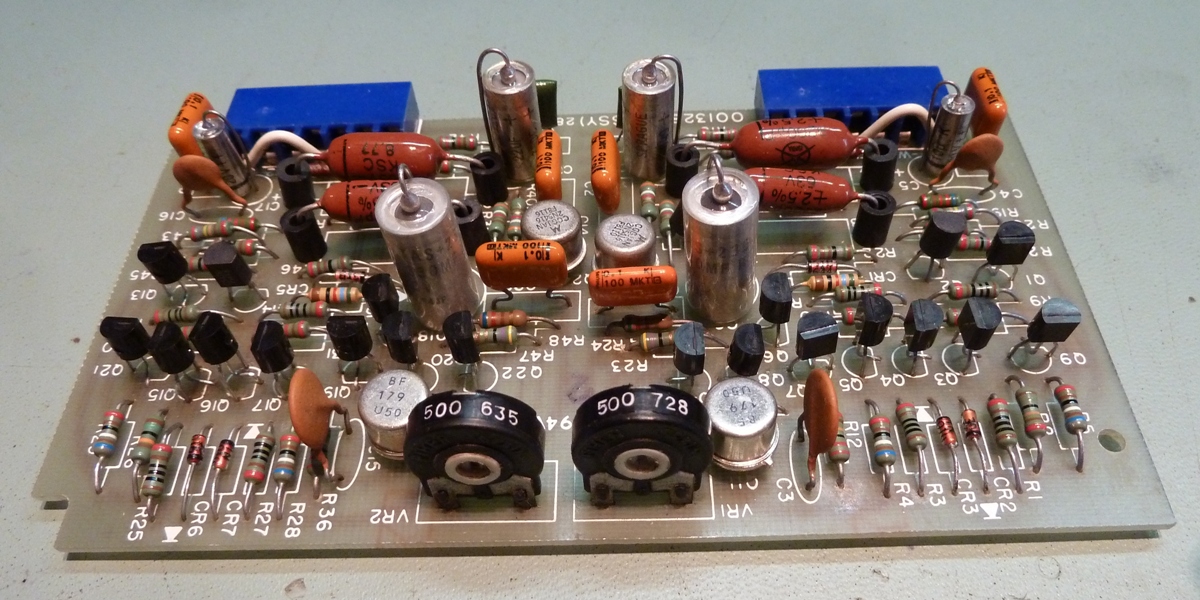
The RIAA correction pre-amplifier.
As on the other cards, all transistors are replaced and also all electrolytics are Sprague 150D tantalums or similar.
Transistors used are: BC550C (Q1,6,8,10,13,18,20,22), BC560C (Q3,4,5,6,7,15,16,17,19,21), BF179 (Q11,23), 2N5416 (Q12,24).
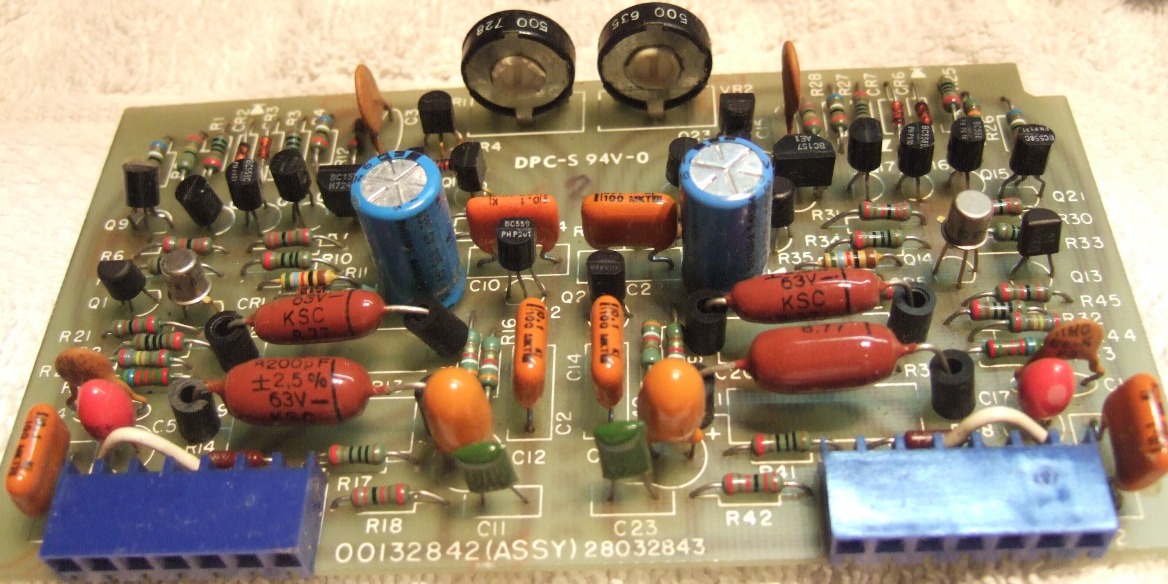



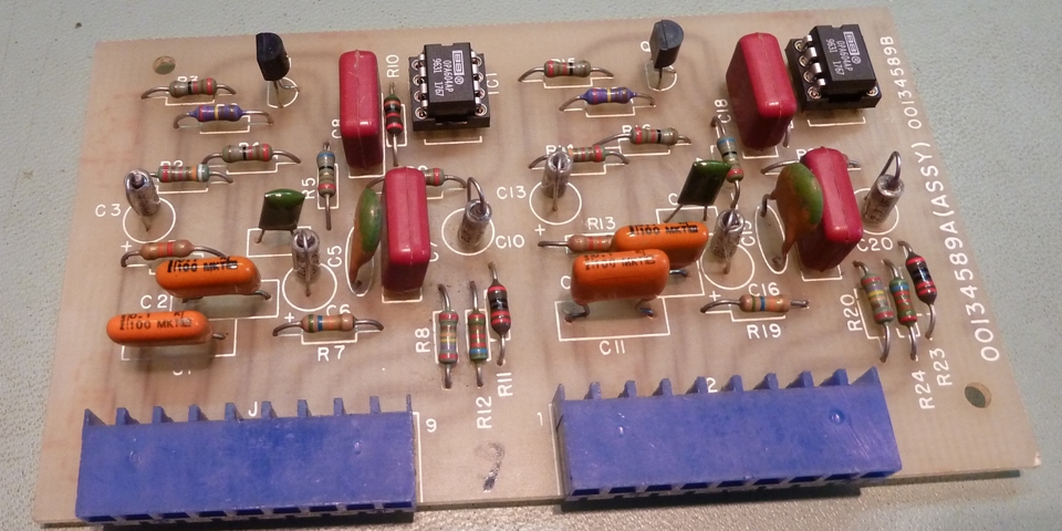
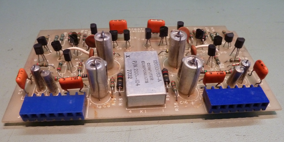
The High/Low cut board and the Equalizer boards.
The high/low cut board sections are in use when appropriate switches pushed in, otherwise it does not funtion.
The transistors BC550C now, the op-amps OPA604.
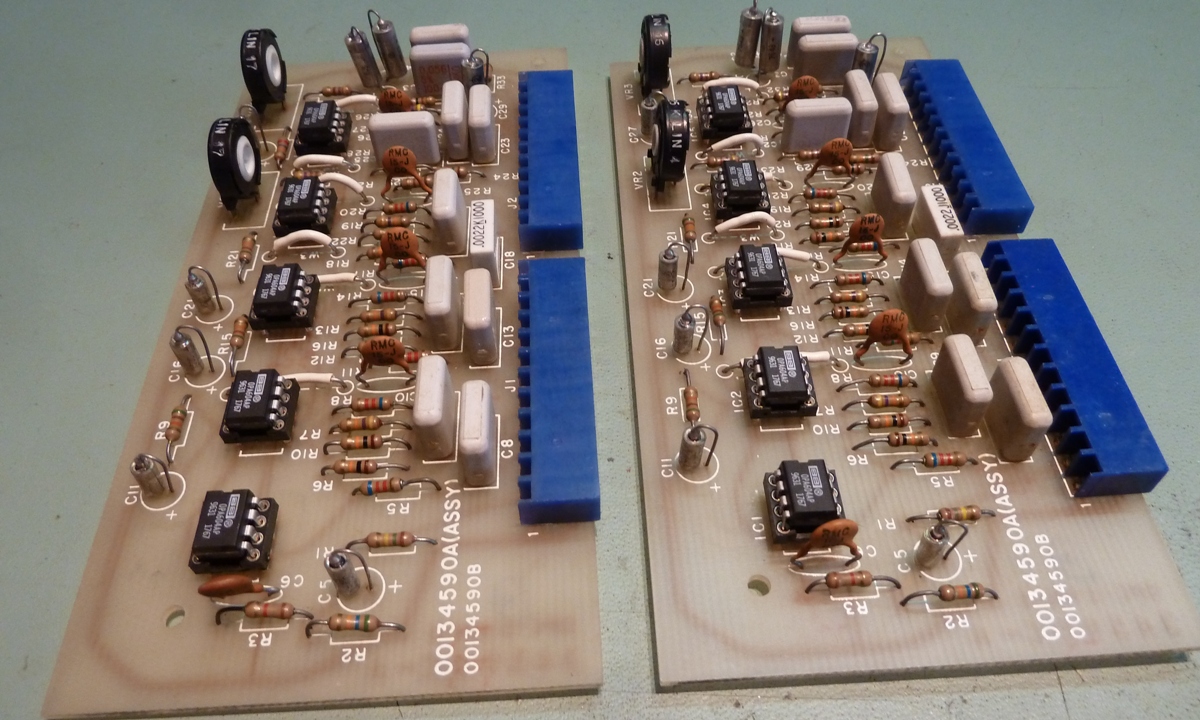
There are two equalizer boards, which also may be bybassed using a switch.
The opamps were replaced by OPA604 as these were available.
Not visible on the pictures yet, the potentiometers are removed since the offset tab is supposed to be connected to the negative 15 volts instead of positive.
Probably they are not needed, but offset is still to be measured.
The equalizer amps do differ in the different schematics to be found on the internet. One uses the CA3100 opamps and the other one uses LF356 opamps, having the offset wiper powered differently. Recently I found during a discussion on Audiokarma, HK did some lousy job mixing board revisions in the actual amplifiers, as this specific amplifier appears to be not the only one having power supply schematic and equalizer board schematic not lining up.



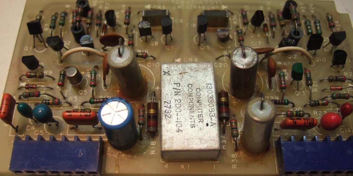
The output amplifier board
The output board amplifies 10 times, however, this was lowered to about 5 times by lowering the NFB resistor from 51.1 to 27.4 kilo-ohms.
The transistors used are: BC550C (Q1,2,9,10), BC547B (Q3,6,11,14), BC640 (Q4,12), BC557B(Q5,13), BC546B (Q7,15), BC560C (Q8,16).



The 50Hz Slider problem.
As there was a sonical problem with the 50Hz equalizer slider, this one was considered defective.
On one channel, it was not possible to "turn up the bass", but it was possible to put it down.
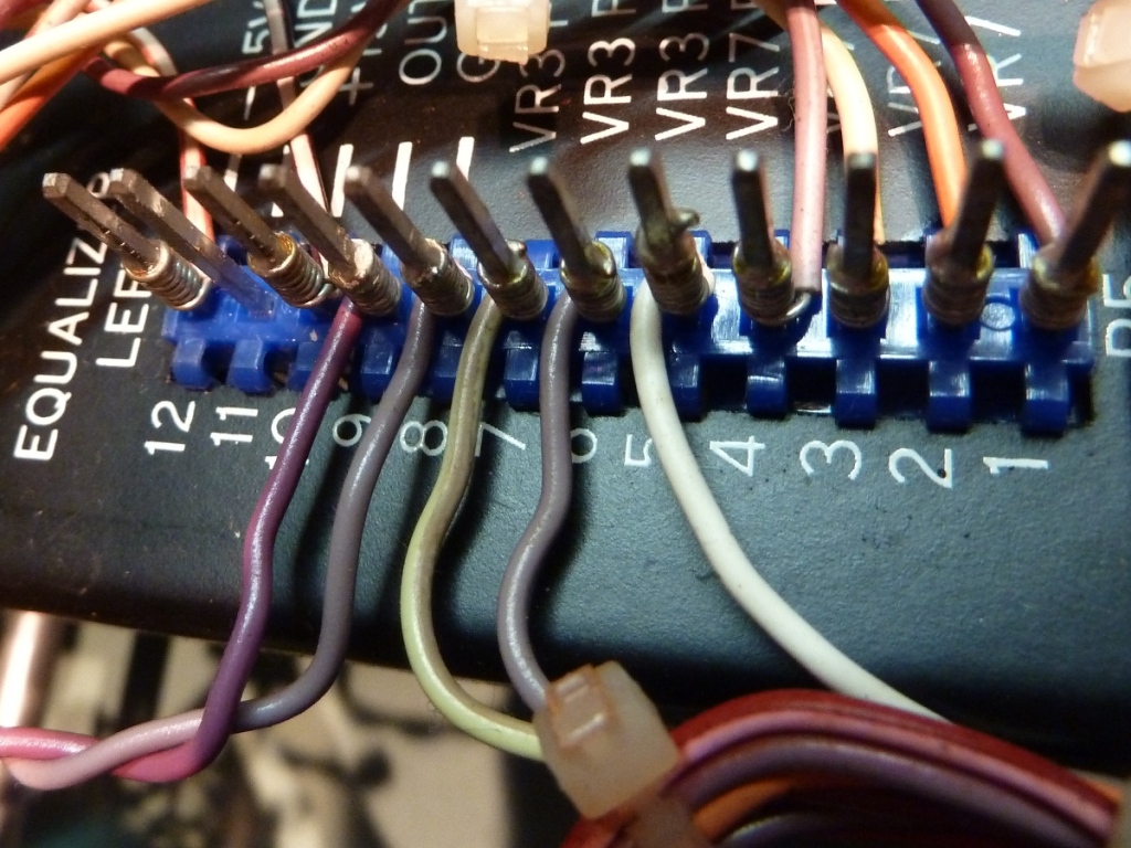
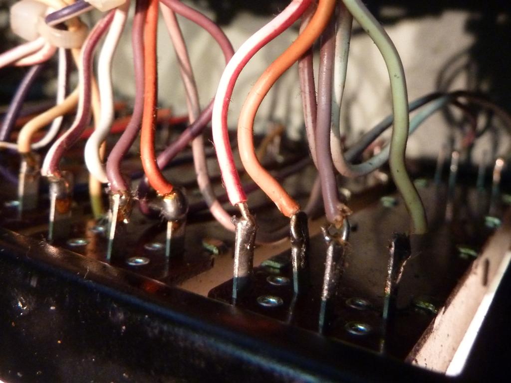
However, measuring showed the potentiometers having two wires mixed up, the pictures are from the mixed up situation.
On the picture on the right, the two wires most forward have to be exchanged. They go to pin 6 and 7 on the left picture.
This means, this error existed already, when the amplifier was new!
It would be interesting to know, if people found the same mistake on more of these amplifiers, as all of my totally three HK Citation devices showed at least one quality control flaw.




The HK Citation 17 .


The service manual of the Harman Kardon Citation 17 is to be found at Hifiengine.
The service manual of the Harman Kardon Citation 17 having the power supply of THIS one is to be found at Elektrotanya. To download it, wait for the "processing" text below the preview to disappear after some time, then click on the "get manual". Do not click on anything else, it does not help you.
Ga naar Gerards page / go to Gerards other pages ---->>> ![]()
