
Leak 3400 refurbishment January, 2023
This Leak 3400 was sold to "thin the herd"
Gemakshalve is deze pagina verder in het Engels geschreven.
![]() This page is written using English language only.
This page is written using English language only.
This nice wide form factor "vintage" Leak 3400 was refurbished and modified, as a leisure project....
It is in my posession for over 10 years already, still performing fine.
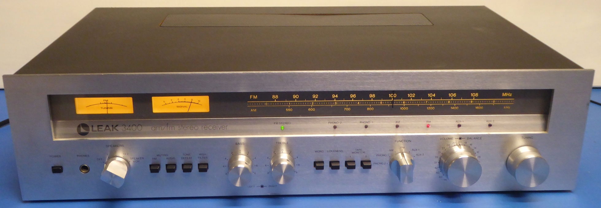
It has a nice thick aluminium front plate. Its knobs are machined solid aluminium, no plastic, here....
The enclosure is covered by some "plastic veneer" stuff. Therefore, after the restoration, I put a layer of polymer "floor protection fluid" on it. The type intended for linoleum, pvc, and alike floors.
I am rather enthusiastic about this product, it just make things looks shiny and newish, without affecting the color.

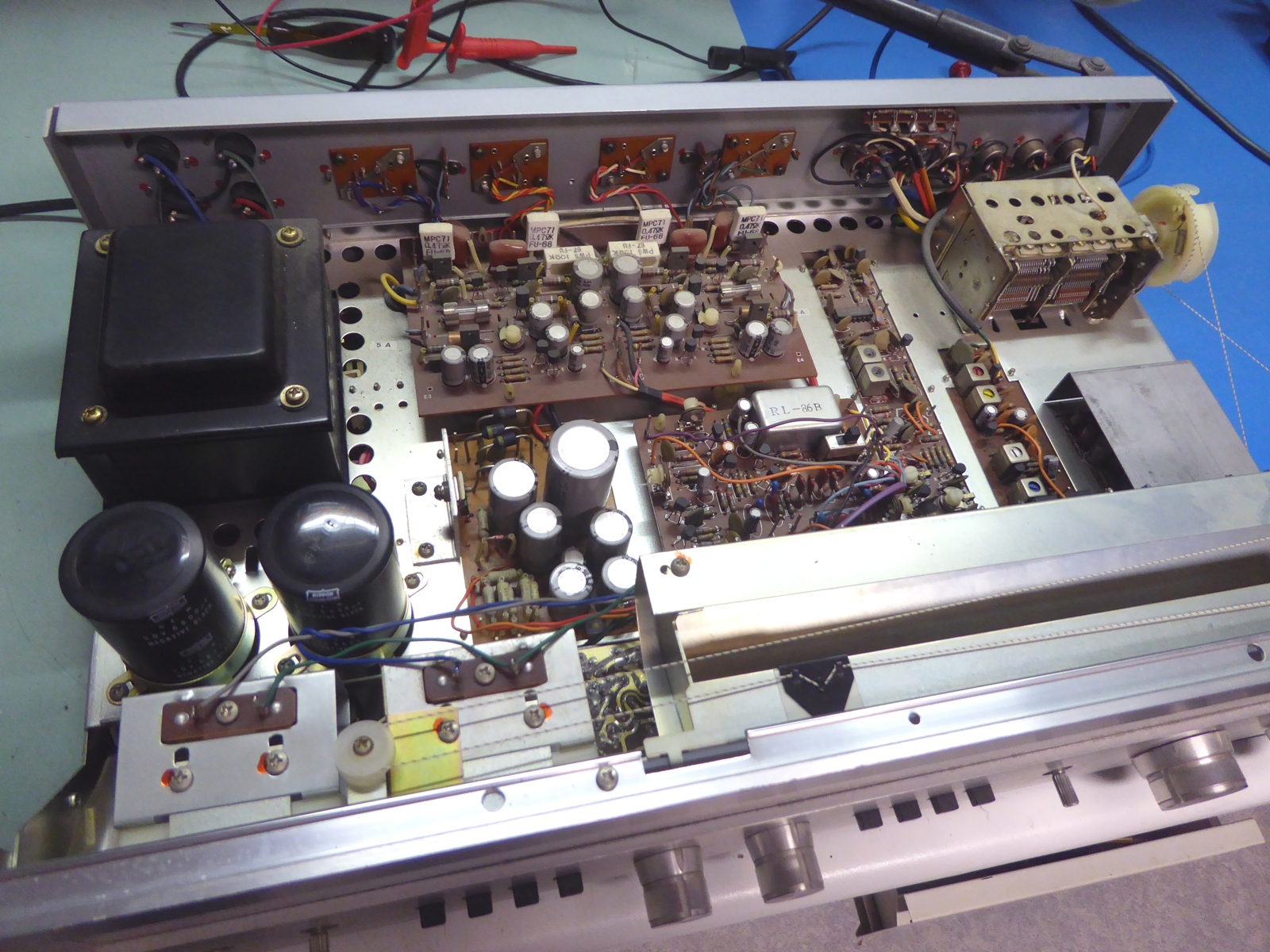
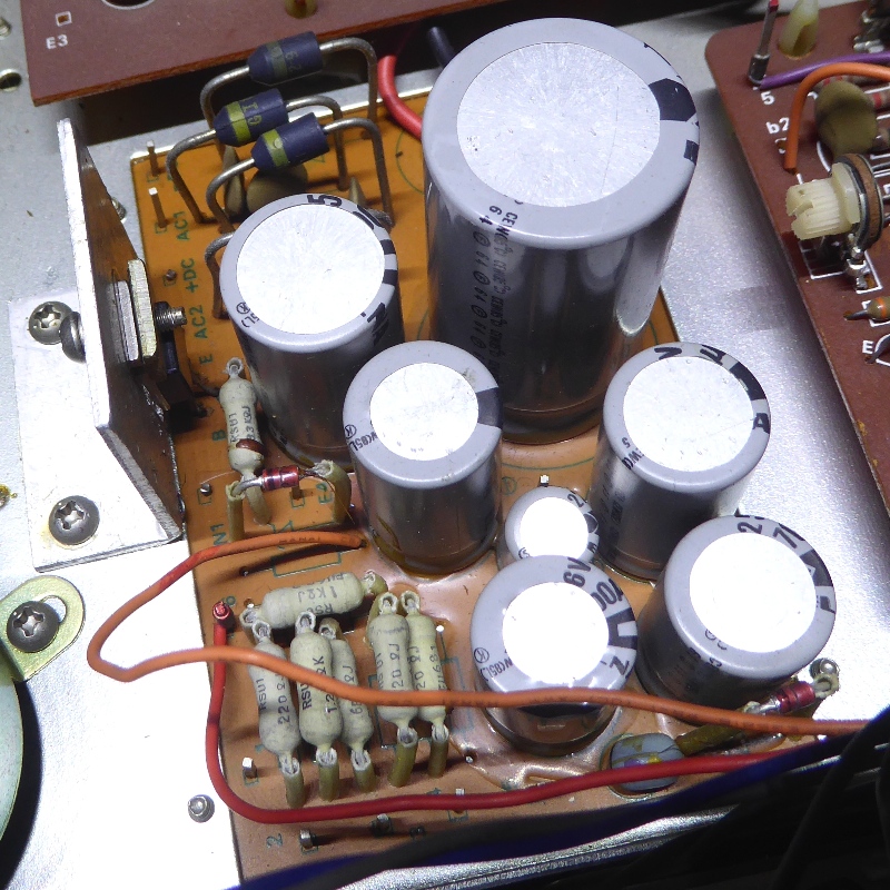
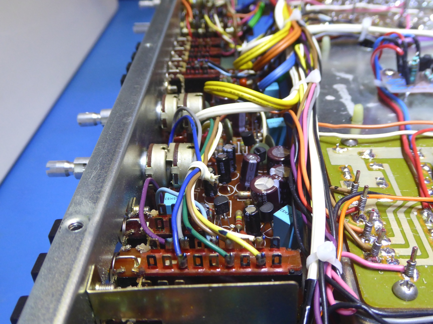
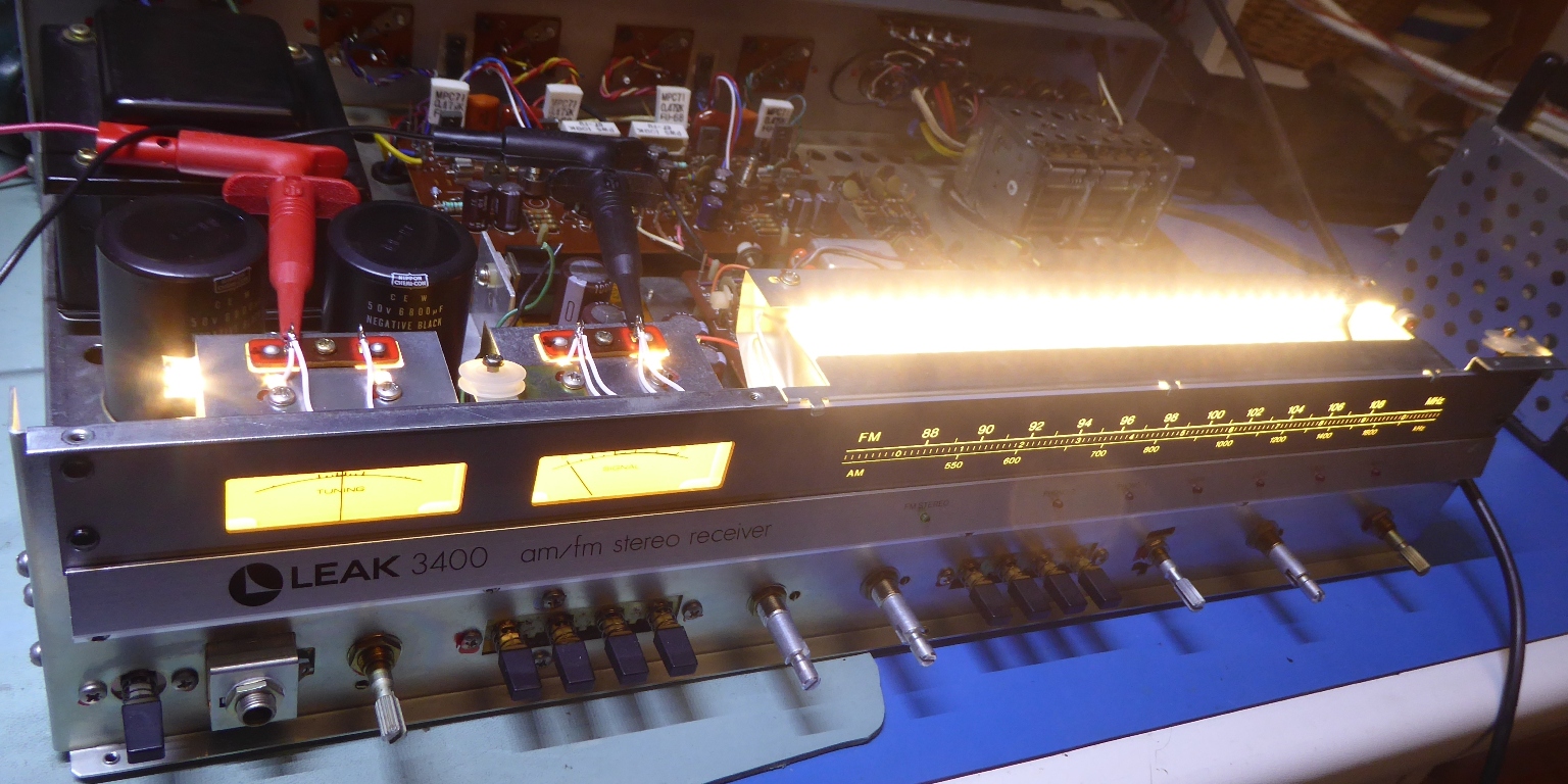
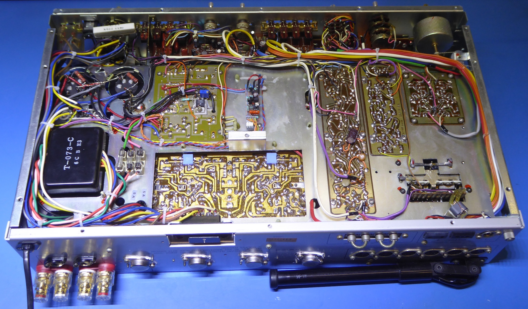
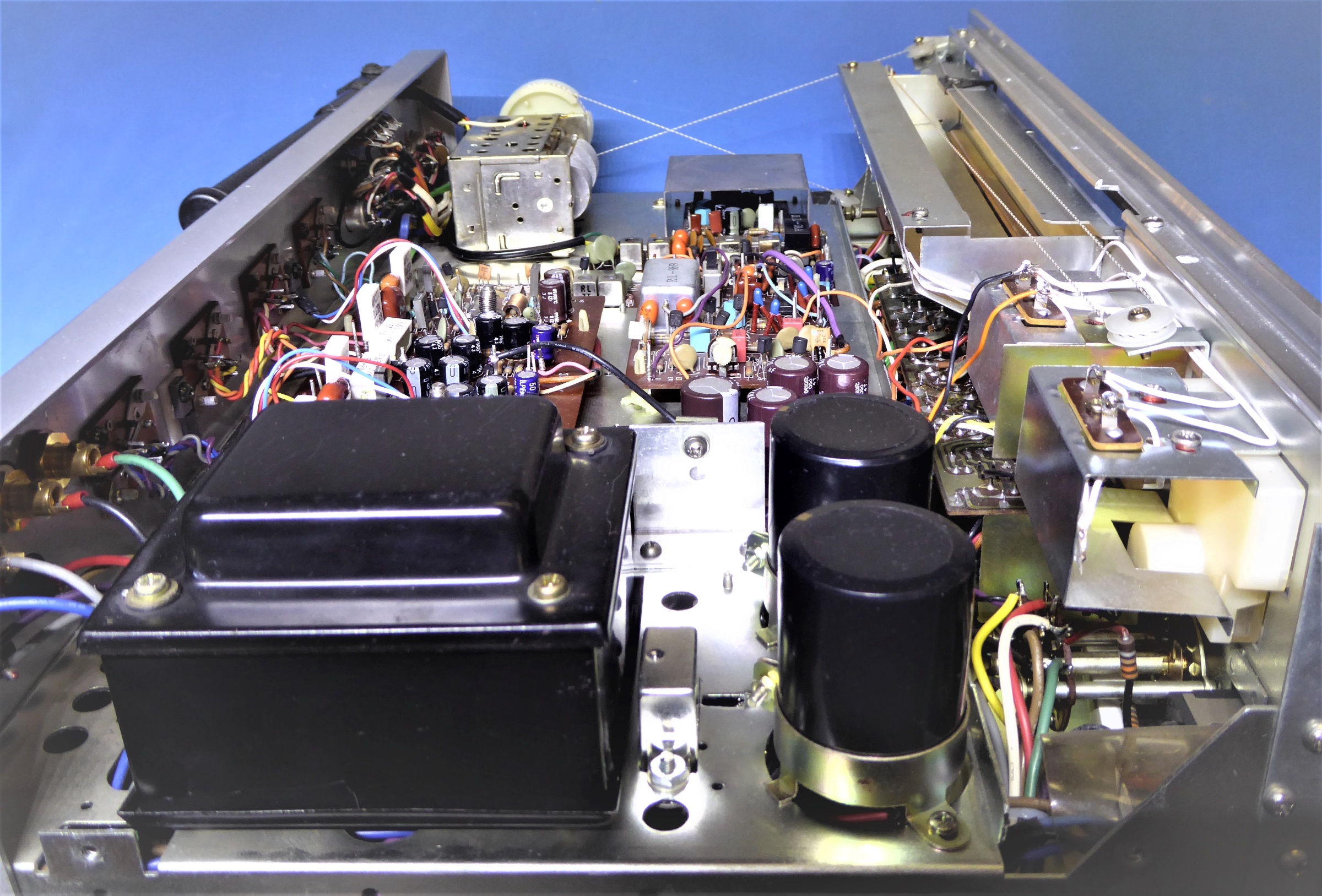
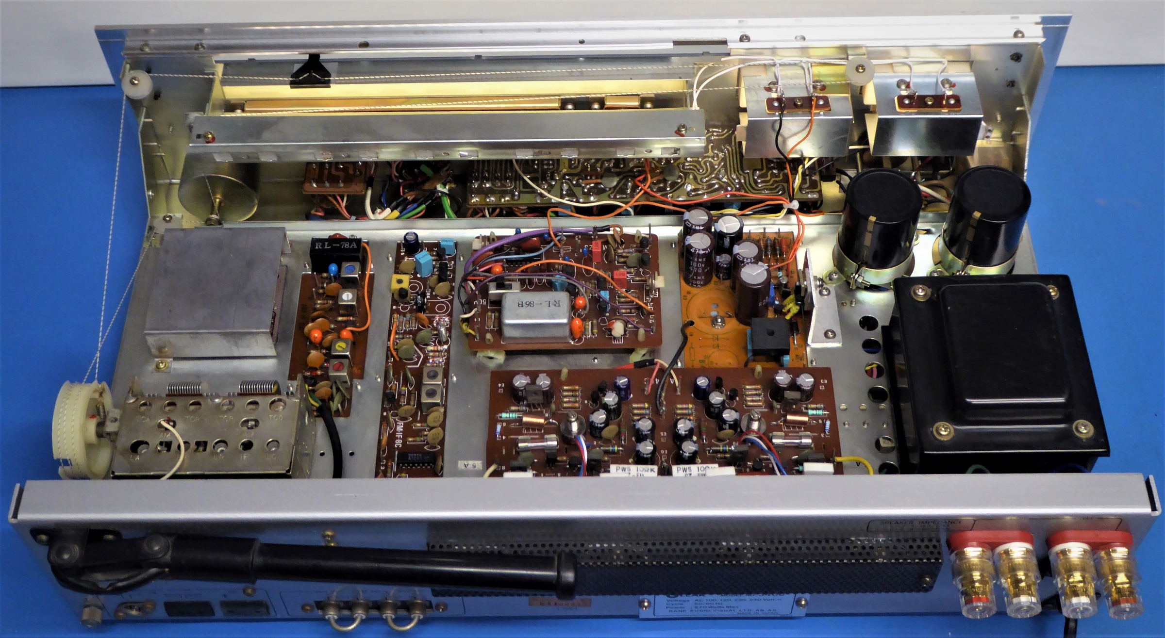
The innards of the not-yet-refurbished receiver.
No mechanical wearout, no burn marks, no weird construction, simply a well designed roomy receiver.
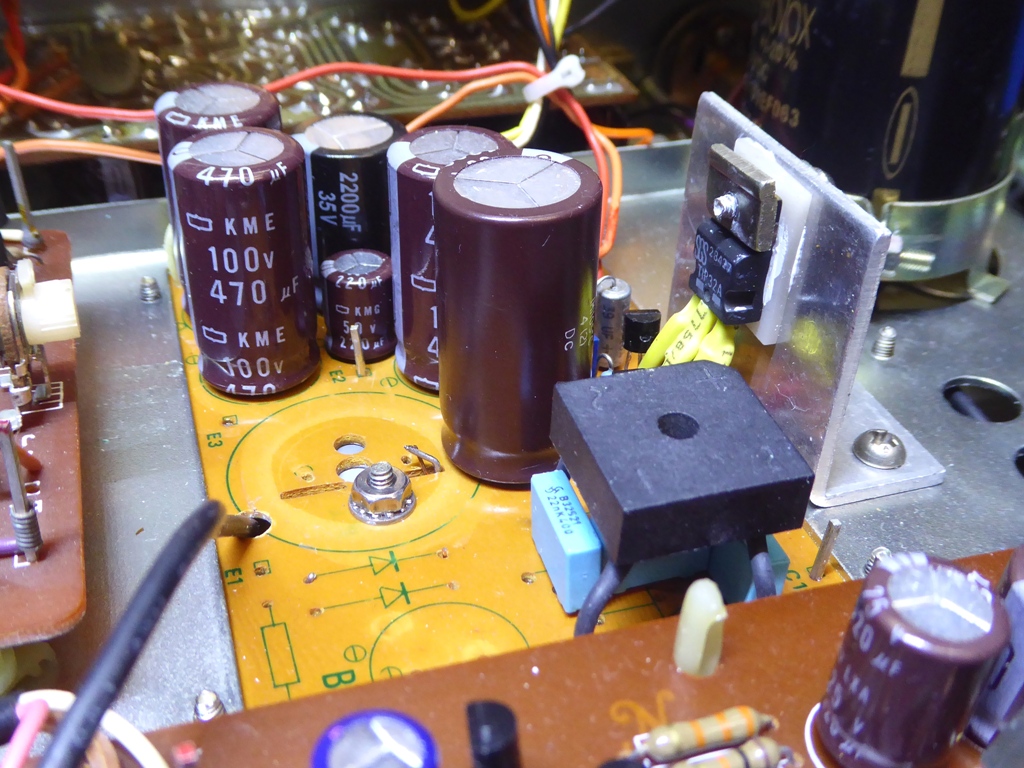
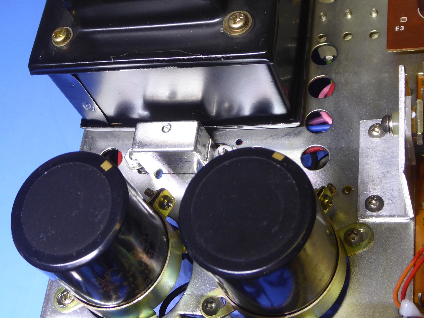
The Leak 3400 power supply
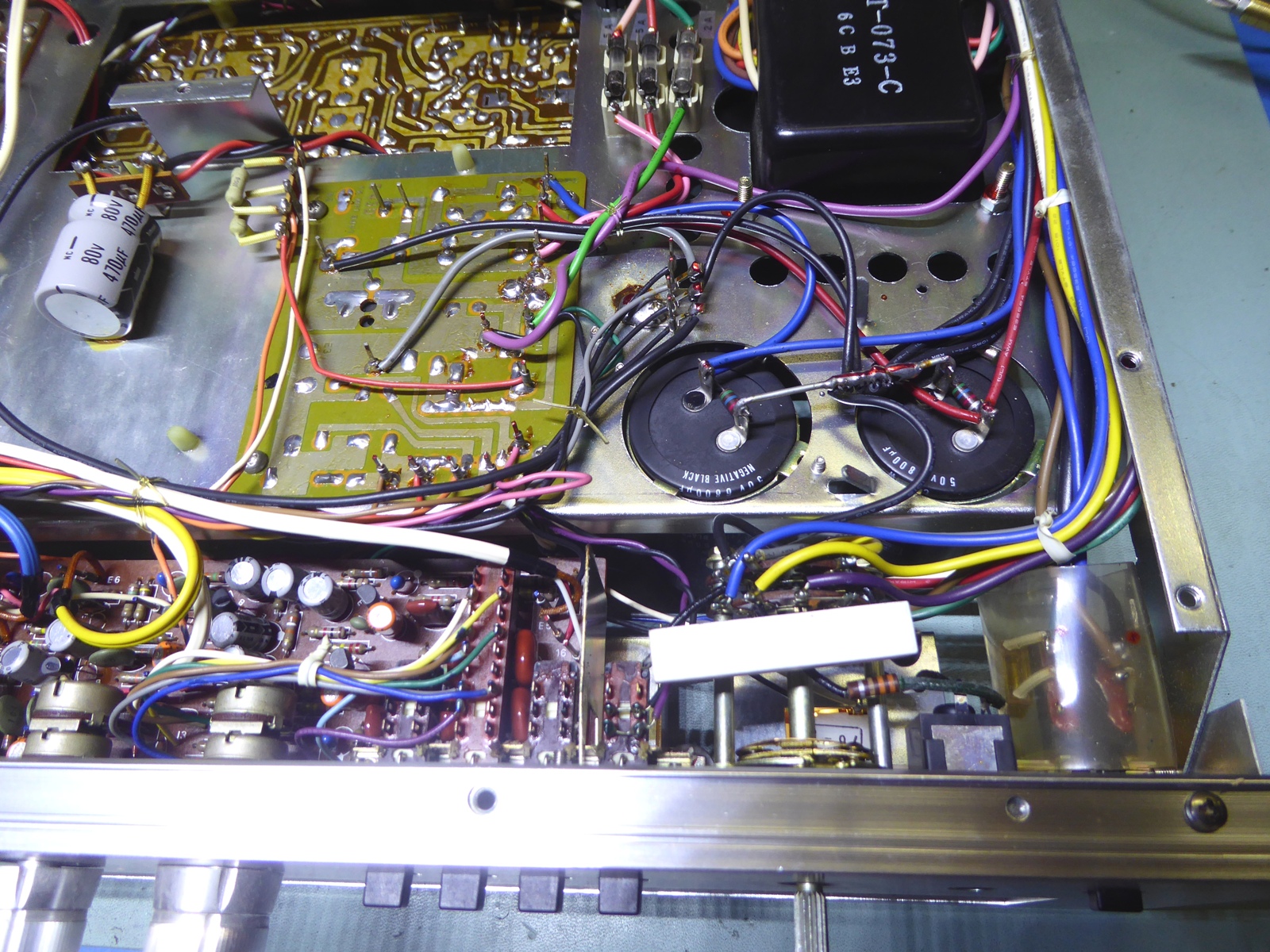
The power supply appeared to incorporate a voltage doubler, apparently the manufacturer decided to take the capacitor off-board and glued it to the bottom chassis.
Probably it was failure-prone, as there is AC current flowing "through it", and it must be kept cool. Now, the series transistor has to get rid of more than 30 Volts making the supply hot. If they had not used this way of rectifying, they could not use the simple way of smoothing power for the preamps.
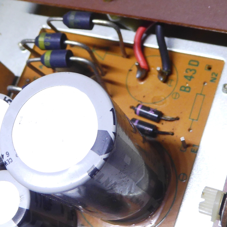
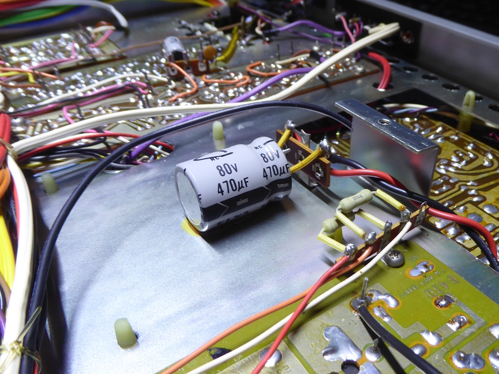
While the middle picture indicates a capacitor location on the circuit card, two leads go down from it, on the bottom of the receiver they go to a big 80V premium quality capacitor, apparently needed.
As it is big compared to voltage and capacitance, it would not fit where they wanted it?
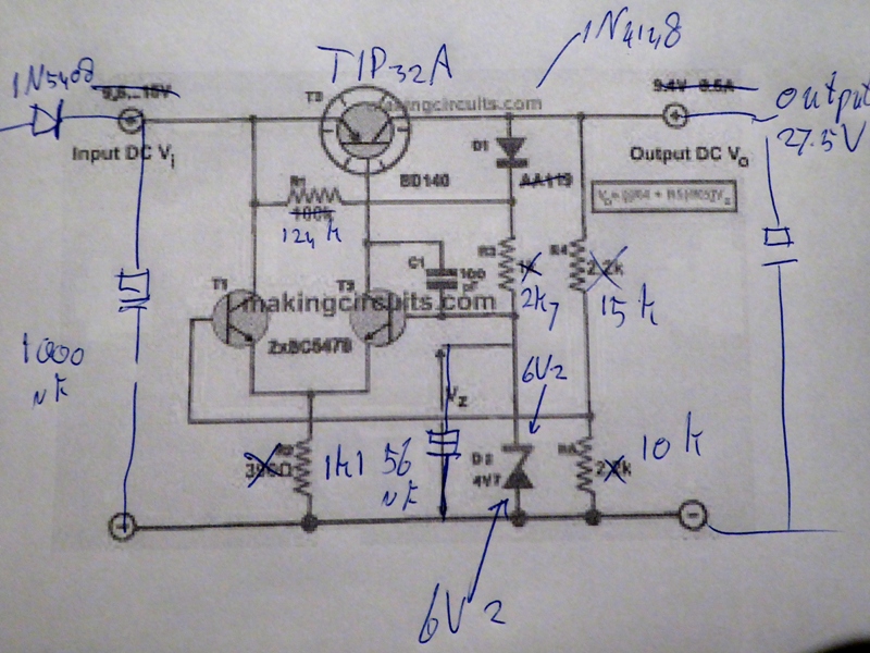
The circuit was modified to get rid of the voltage doubler and excessive heat dissipation.
Wanting to make a low drop regulator, I wanted to use a PNP series pass transistor.
The easiest way to draw it up was taking an suitable schematic from the internet and adapt it to the desired voltage (27.5 Volts).
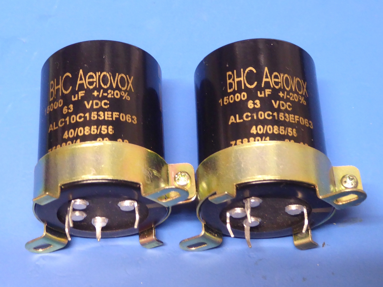
New premium type 15000 microfarad Kemet ALC10 power smoothing capacitors were used, a generous amount of capacitance, and about the best type one can get for longevity. No compromises, here.
Therefore a more capable bridge rectifier was needed than the 3 Amp diode set used (at least to my own standards), originally, it resides on the power suply board where the diodes were.
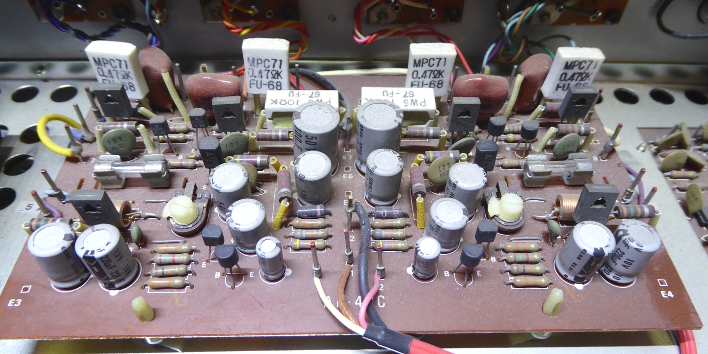
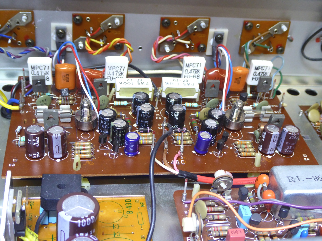
The power amplifiers board
It was a little bit dusty, but still in good shape and working, before restoration. I know, some will comment "If it ain't broken, do not fix it"....
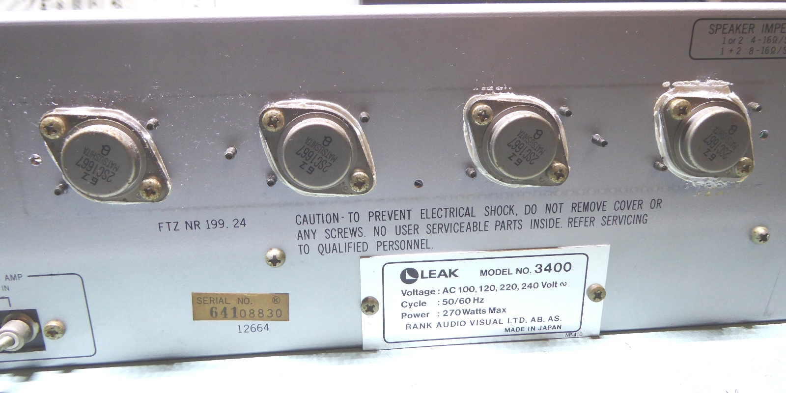
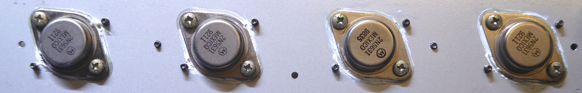
The old big output transistors are still good but HFE was on the low side. Wanting no compromise, I replaced those by 2N5631.
This, since a two-transistor current stage could be compromised (read: start distorting) when power and frequency are towards maximum and HFE is (or may be) not sufficient. Apart from that, the 2N5631 is more sturdy.
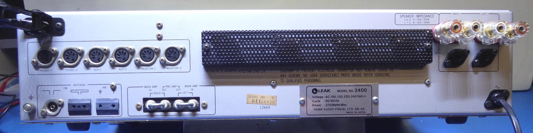
Notice the type identification plate: the receiver is made for the Rank conglomerate. Removing this plate, it reveals the "voltage selector plug". I kept it at the 220 Volts setting, to gain a few output watts (mains is around 230 Volts, in the Netherlands).
This is no problem at all for the now more sturdy power supply and amplifier section. The result at 230 Volts input power is, one will have about 1.5 Watts extra per channel, instead of 1.5 Watts less, when the plug would be set at 240 Volts instead of 220.
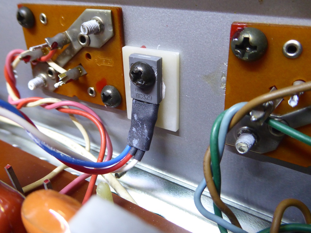
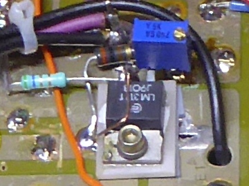
The Quasi-Complementary power amplifiers used a double diode pickup mounted on the heatsink, it was routed to a VBE multiplier transistor on the circuit card.
As the incorporation of a "baxandall diode" has benefits only for distortion levels, I implemented it.
I mounted this VBE multiplier transistor BD329 directly on the heatsink, using a heat-conductive ceramic insulator, and adapted the circuit to the new situation.
Pins 4 and 6 did get a 3k83 resistor in between, it attaches to the base and collector of the BD329.
The diode hides behind the PNP driver next to the emitter resistor of it, this resistor was 22 Ohms originally, but while the diode is in parallel, it is 330 Ohms, now.
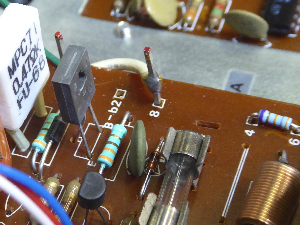
The power transistors, they are 200W types suitable for amps up to some 100W / channel, so they have a very easy life, here.
Other new parts were used as thought appropriate, having technical quality and longevity in mind.
The trimming potentiometers used for the bias (aka quiescent current) setting, are high reliability metal sealed ones, now.
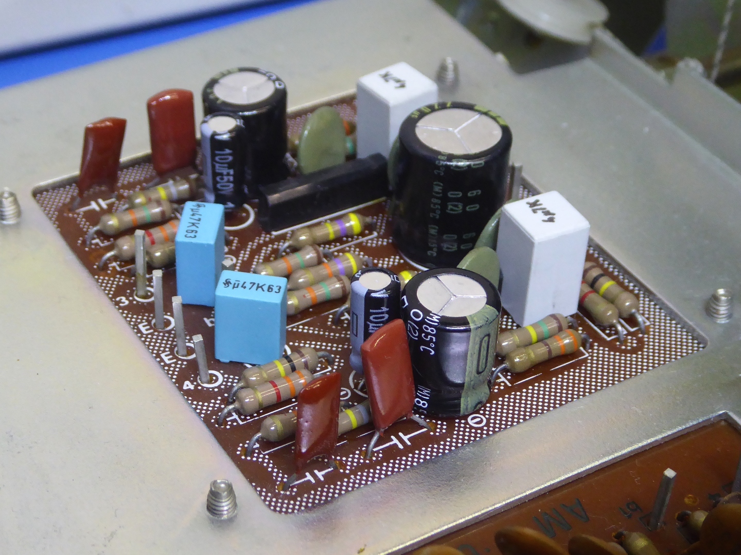
RIAA input circuit card.
This card has a metal shield mounted, it is not shown here, to be able to make the picture.
It uses a chip designed for the very purpose of being used in this kind of circuits, there is not much to be gained here and just five electrolytic capacitors were replaced using ones assumed a good choice.
The other four electrolytics, for in and output, were replaced by film capacitors, considered superior compared to electrolytics in these positions, those are the square looking ones.
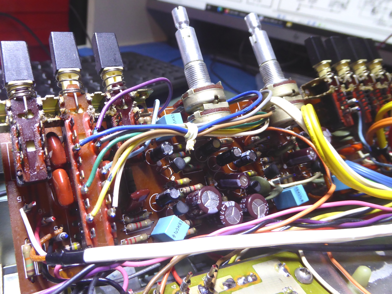
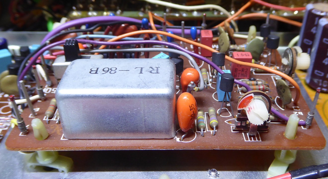
Pre-amplifier board.
I forgot to take pictures of this part of the recap, also here this was capacitor replacements only.
As all front panel potentiometers and switches still operate very well, these were untouched (not cleaned).
As on the RIAA card, the blue rectangular ones are film type capacitors, instead of electrolytics.
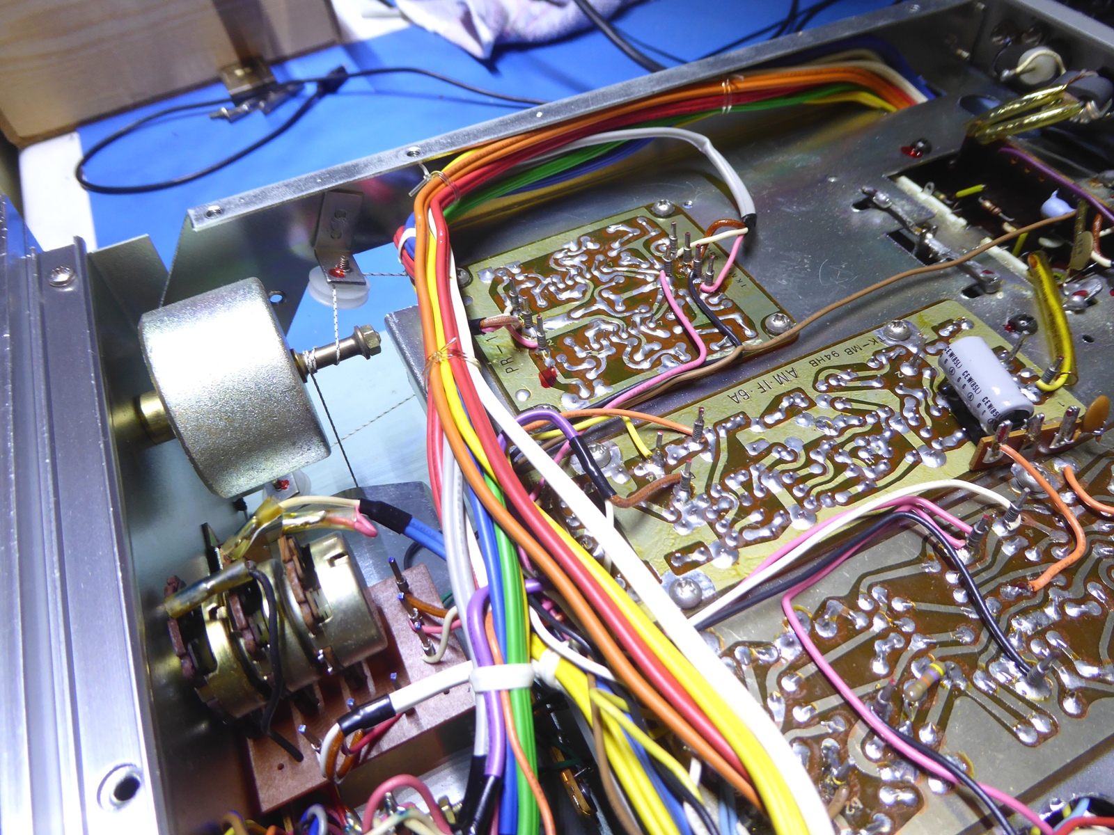
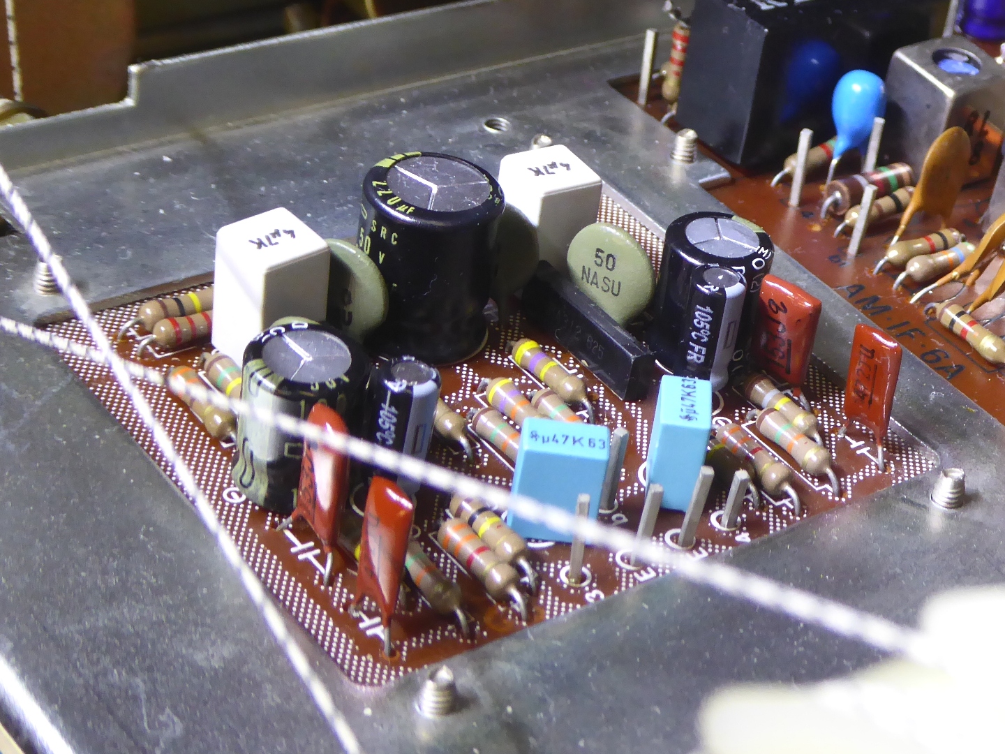
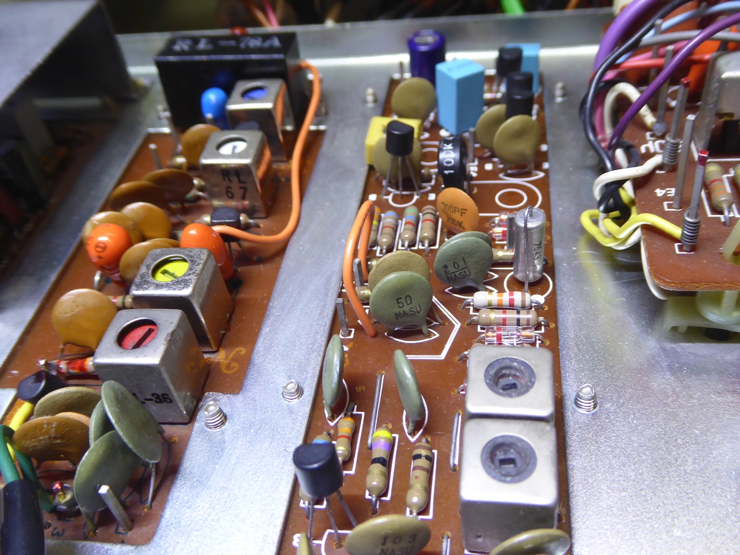
The Tuner boards.
The tuner related AM / IF /stereo decoding circuit cards did get a recap for the aluminium electrolytics only, using parts I considered appropriate.
The actual FM tuner front-end is a so-called 4-gang sealed one, it gives good reception, even using a piece of wire as antenna.
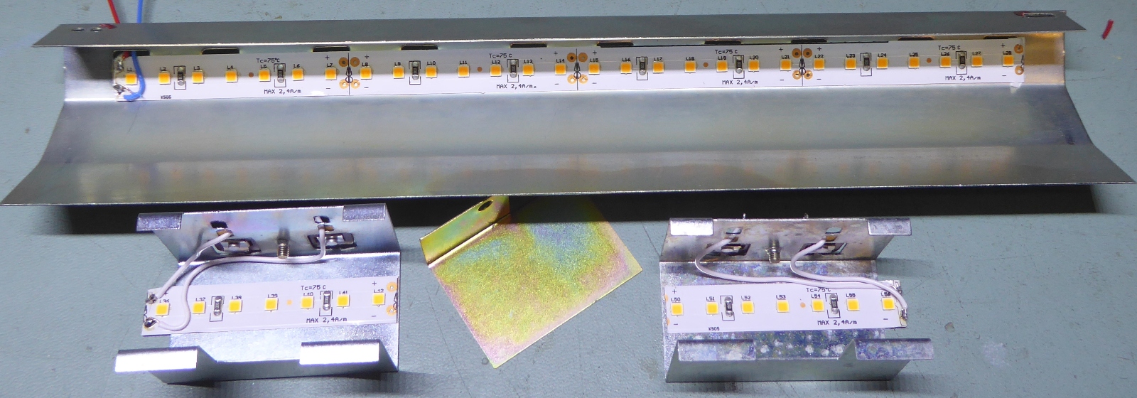
The receiver backlighting.
The old lighting was still working, but some lamps were blackened already. "No-brand-name" replacement lamps do exist, but they are of inferior quality and no "brand name" lamps are to be found, anymore.
Therefore, it is better to opt for the LED-string way.
Also reducing the power consumed by lamps just means more power available for the main amps from the transformer! The LED longevity is expected to be infinite as they are employed way below their maximum curent.
There are the two meter mounting brackets, and the tuning scale backlighting, now both carrying the led-string pieces.
The LED string pieces stick out a bit at the meter brackets, as they have to be cut against the marks provided on the LED-string.
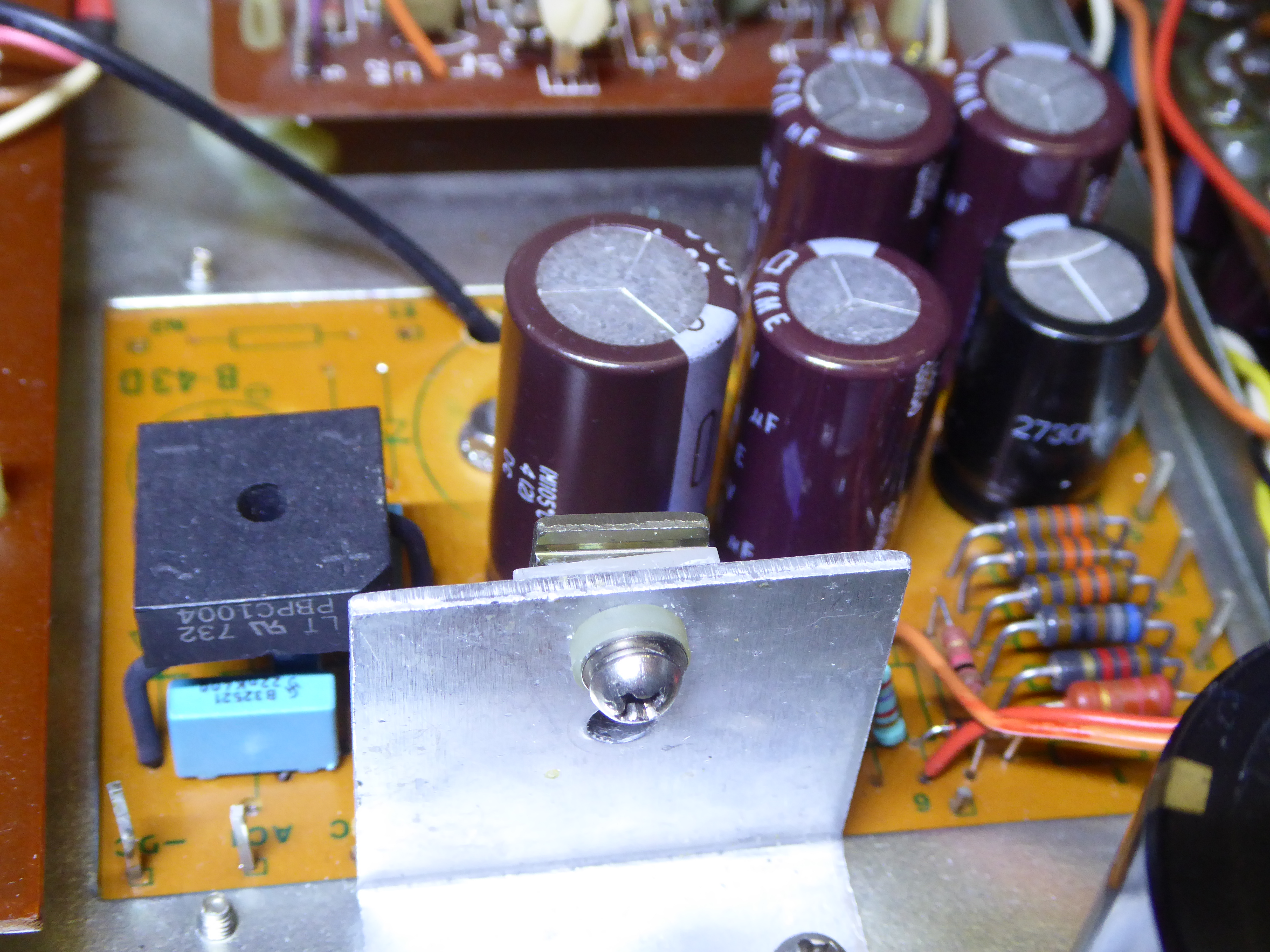
The color is warm-white "2700k", making it look the same as it was. A LM317 adjustable voltage regulator is mounted on the bottom of the power supply card, to provide adjustable-to-demand LED intensity.
Testing brightness versus voltage and current, and the LM317 on the bottom of the power supply board. As can be seen, it can be tweaked up to chrismas-tree level some people like, but too much light would just be distracting....
![]()
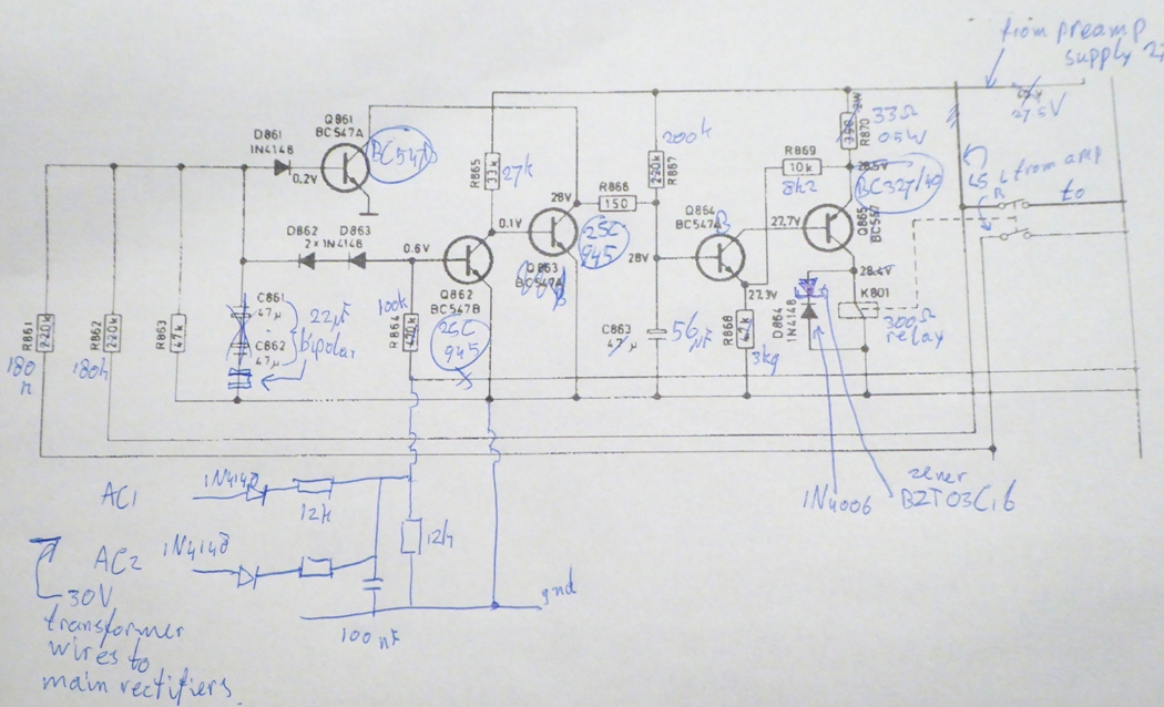
The Amplifier protection circuit.
This receiver did not employ any loudspeaker protection, so I decided to add it.
Having "diggen" many protection designs and most dismissed, several possible known solutions were were evaluated:
- Buying a generic (always Chinese) "ready-to-use" one, but apart from unknown design, the adaptions always needed and the questionable quality, made me abondon this idea quickly.
- The solutions described on the well-known Elliott Sound Products DIY internet pages.
- The one used in many Pioneer amplifiers and receivers, versatile and repeatable.
- The one I used before, alike the Tandberg TR2080 one. I did choose this layout again. It is very alike the Pioneer ones.
The schematic employs DC detection as well as AC-loss detection to immediately switch off the relay when the receiver is switched off or looses power from the outside. An extra zener diode in the relay snubber circuit dissipates energy to enhance switchoff speed at the very moment the relay is supposed to disengage.
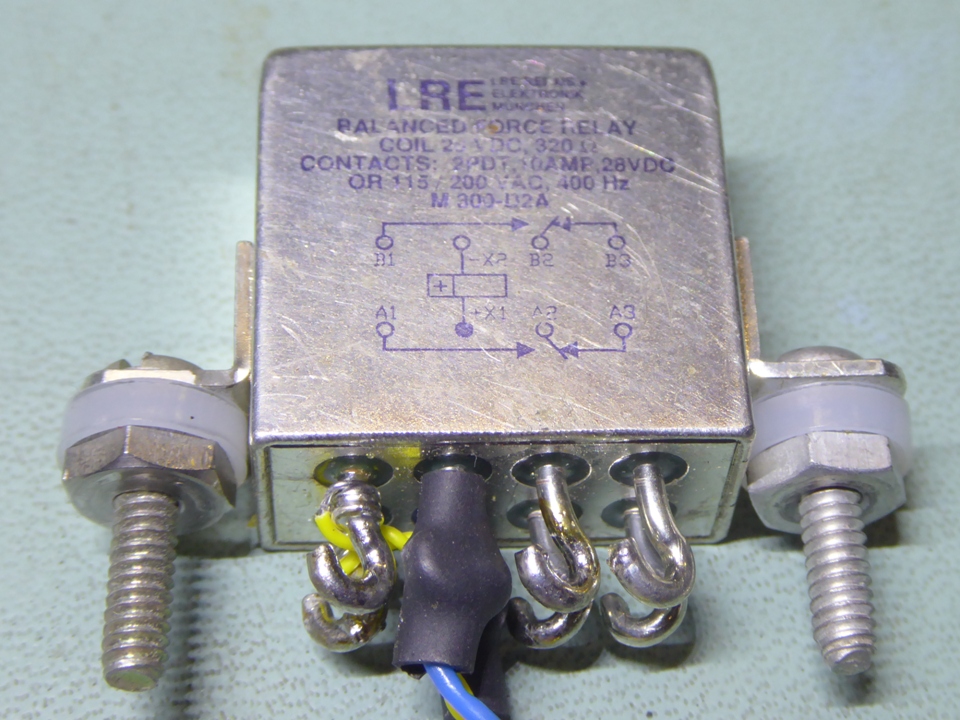
- A totally sealed LRE 10 AMP avionics relay is used, it is mounted in between the power transformer and the power smoothing capacitors.
It fits nicely between the transformer and power smoothing caps, often called "Filter capacitors" (whatever.....).
Even in used condition, these relays average above $50,- on ebay .....buying a new one, probably $200 incl tax if buying one only at a reputable source.
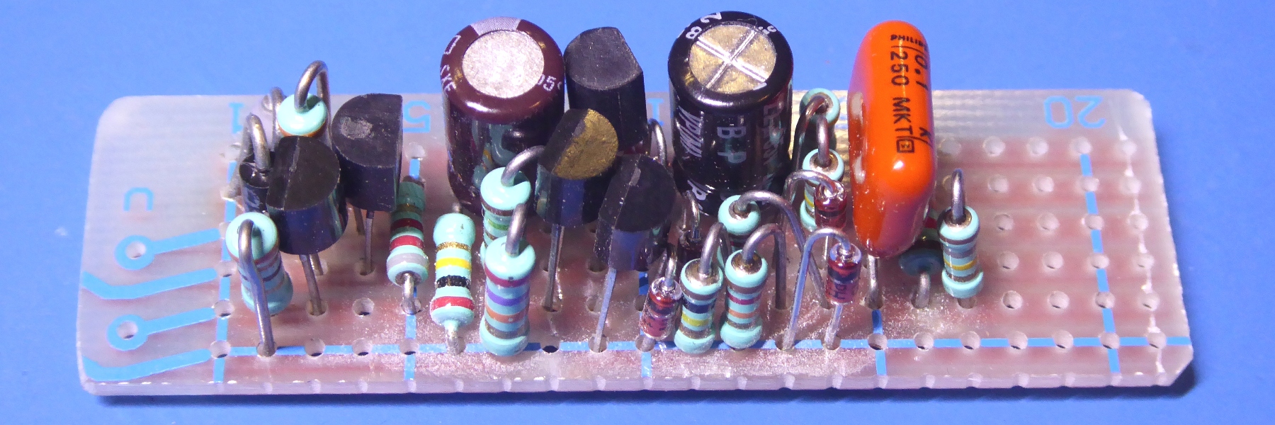
The stripboard, containing the circuit. I managed to keep it very small. Even transistor selection was done with the pinout versus mounting location in mind, to get the smallest footprint considered the parts used.
The back of the receiver.
Whereas no decent DIN loudspeaker connectors are to be found anymore, a set of others was mounted.
The bottom.
The side.
The top.
The Front. The receiver does not look that big on the picture, but it is quite wide.....
Ga naar Gerards page / go to Gerards page ---->>> ![]()