

Luxman R1500 refurbishment September, 2022 
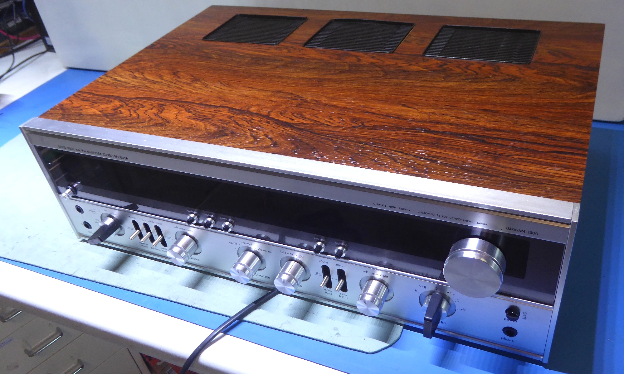
This R-1500 was sold (2023?), because of having no room for more and somehow new projects enter my house.


Gemakshalve is deze pagina verder in het Engels geschreven.
![]() This page is written using English language only.
This page is written using English language only.

This Luxman R1500 was sold to me some years ago as "does not receive, after being repaired and recapped".
It was bought from a tech, who apparently gave up on it. He was not the one recapping I was told
Apparently, this recapping only involved replacing some capacitors in the power supply by elcheapo types, probably years ago, as there was physical leakage already.
this leakage was indicated by a few greenish capacitor leads.
Apart from it being dirty, there was no sound and indeed no reception.
It was decided, to do a rebuild using separate steps, so everything could be tested in a working unit.


The Luxman R1500 power supply
The power supply card PB758 was to be refurbished first.
It did appear to have a defective Zener diode, supposed to supply the 12 Volts for the tuner circuits.
Apparently, it was repaired before, and while a 12 Volts type of zener was used, apparently it clamped the voltage to some five Volts instead of twelve Volts. The guy putting it in, may have not been aware his new zener was defective, already. I do not know if the seller I bought it from was the one putting it in....
The earlier sloppy repair and use of elcheapo brands capacitors reflect the "average" "repair quality" done by hifi shops.....I know, their customers expect repairs to be quick and cheap....
The amplifier protection circuit also resides on this voltage regulator card.
Apart from the other parts, also the protection relay was renewed, it also includes a relay socket, now.
The card discoloring indicated the power circuit series pass transistor went hot in the past, therefore I abused a ceramic heat conducting TO220 mounting washer as a "heatsink".


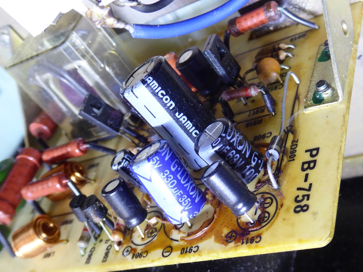

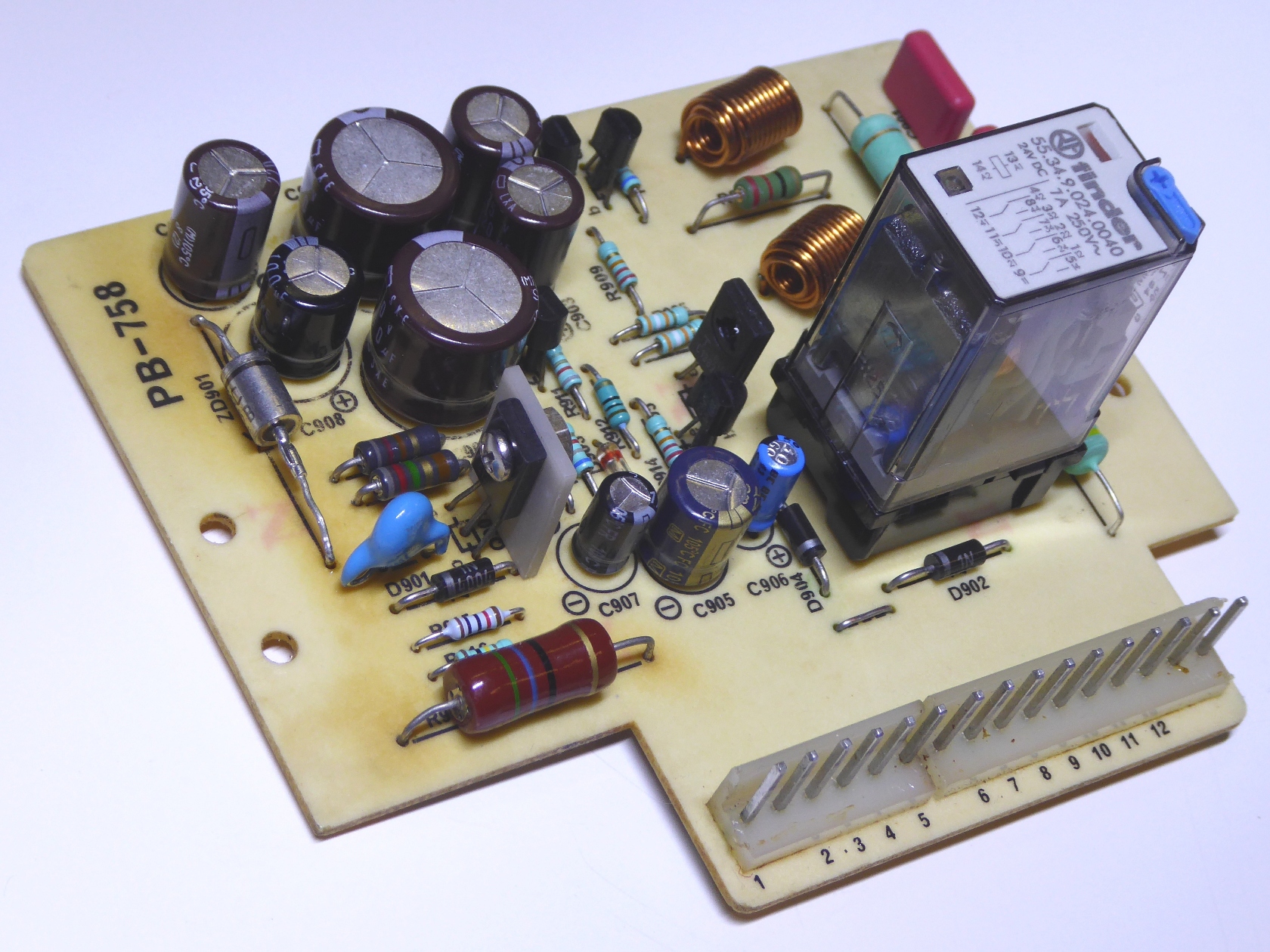


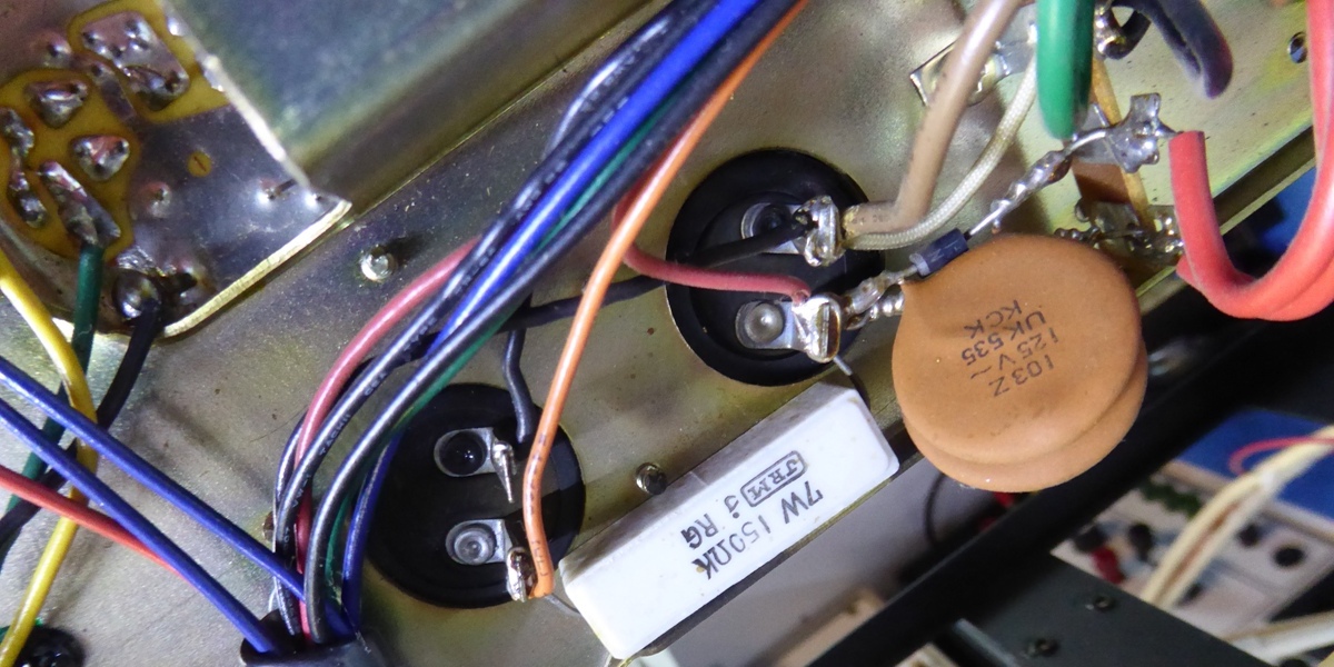
The rectified voltage for the preamp supply also feeds a big resistor, supplying some 20 Volts additionally to the PB758 board where it is further feeding a resistor going to the said Zener diode.
As this source was to be used for LED scale lighting, this circuit was modified.

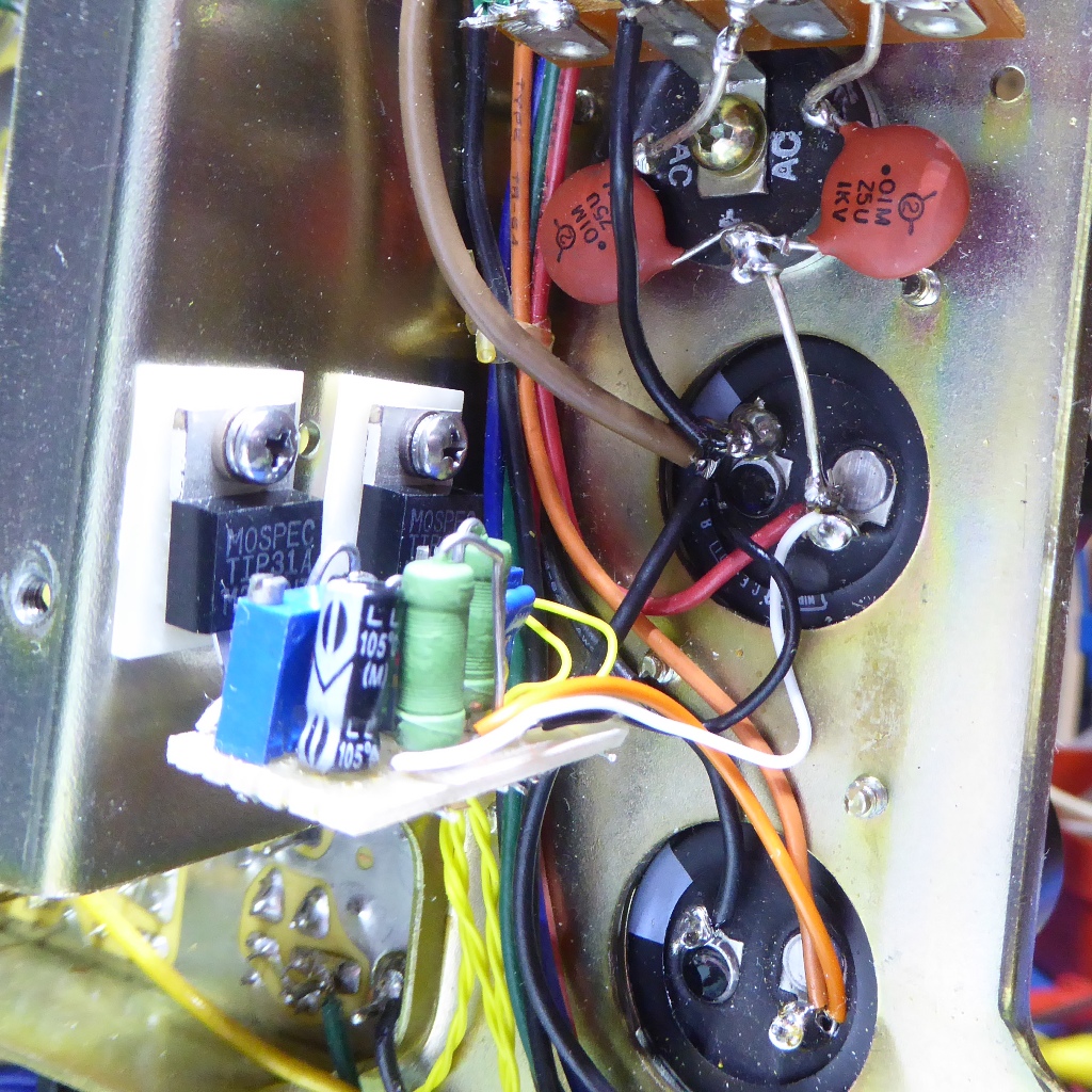
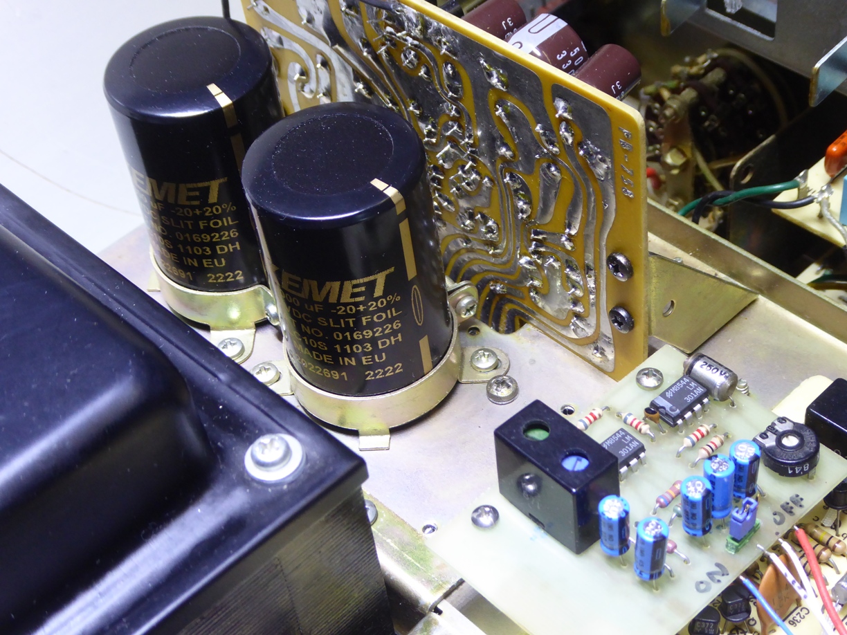
The 3300µF and 1500µF smoothing capacitors were both replaced by scavenged newer 6800 microfarad ones, and the diodes by a far more sturdy round bridge rectifier.

The big resistor was taken out. I replaced it by a little circuit including two bolted down power transistors, they were used as attachment of this circuit.
This circuit supplies the tuner voltage AND the LED lighting, it consumes some additional 120 milliamps / 5 watts total including LED lighting.

The original lamp wiring from the transformer is not in use anymore, saving 18 watts of lamp power, leaving a 13 Watts power usage benefit.




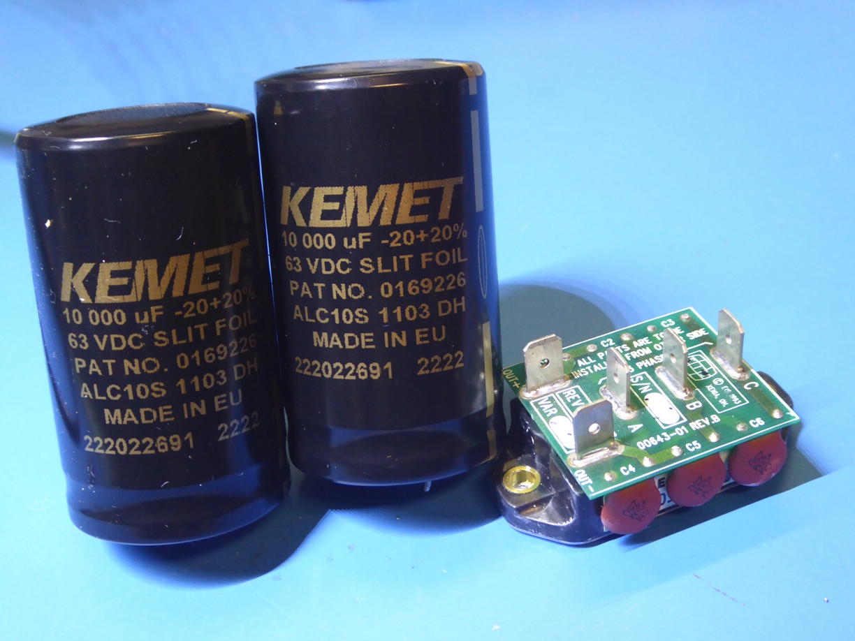
The two big smoothing capacitors were replaced by top quality new 10000 microfarad ones
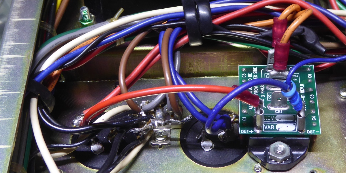
Wanting to use a bigger rectifier, the mounting strips carrying diodes and snubber caps were replaced by a single heavy duty 30 Amps module, which was scavenged from professional equipment.






The power amplifier boards PB760
The power amplifier modules were taken out and bench tested using a +/- 35V power supply. One was good the other one had some 5% distortion.
Observations:
- the distortion
- both had a unknown-brand npn driver TO66 transistor
- one ever had a 47 Ohms resistor replaced where NO technical fault ever could cause a 47 Ohms resistor to burn....
- some other burn flaws
- protection circuits diodes were cut out, maybe to ease repair, or maybe for "technically unsupported audiophile reasons" (maybe even by Audioscript, its importer company)

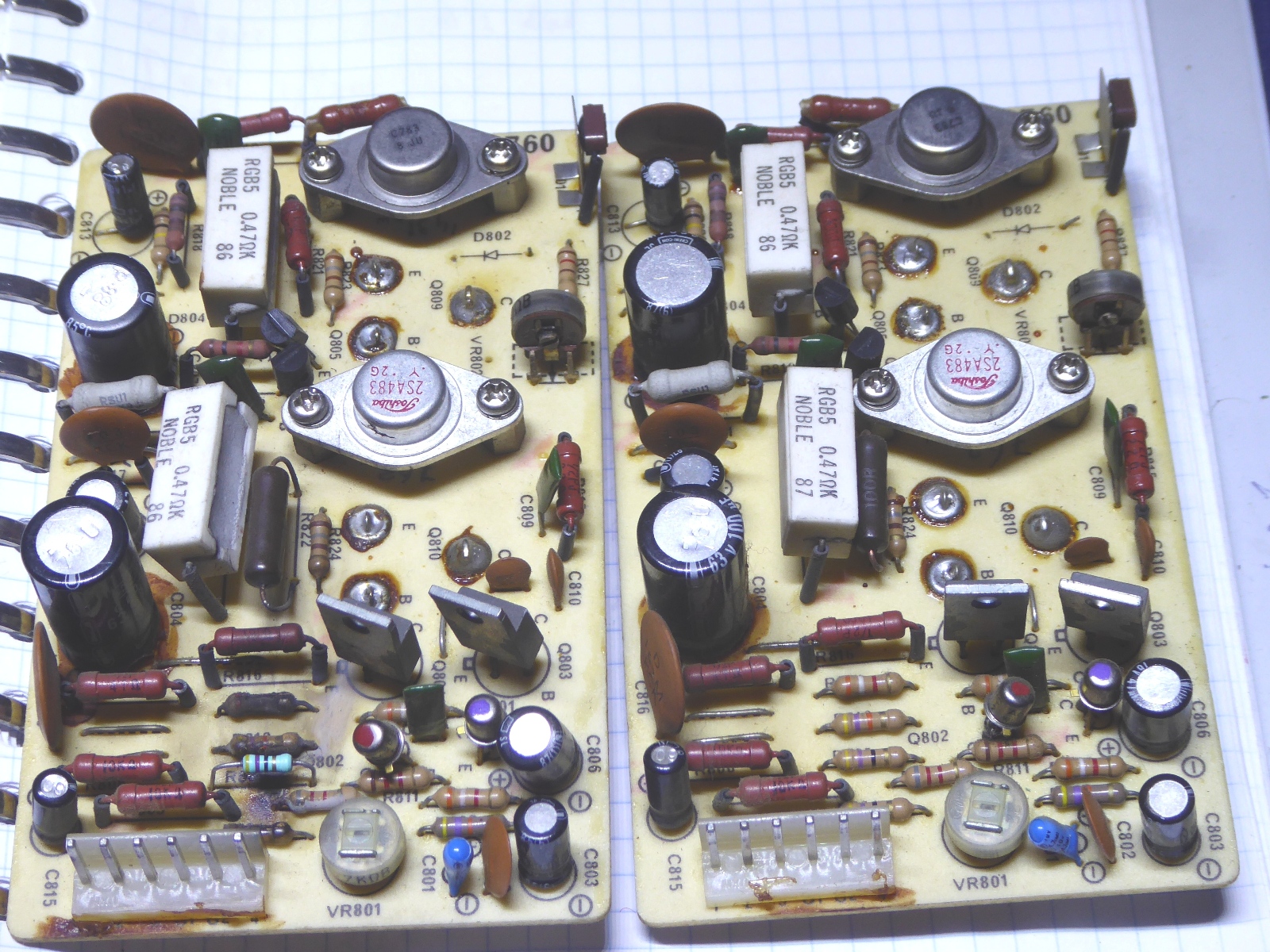

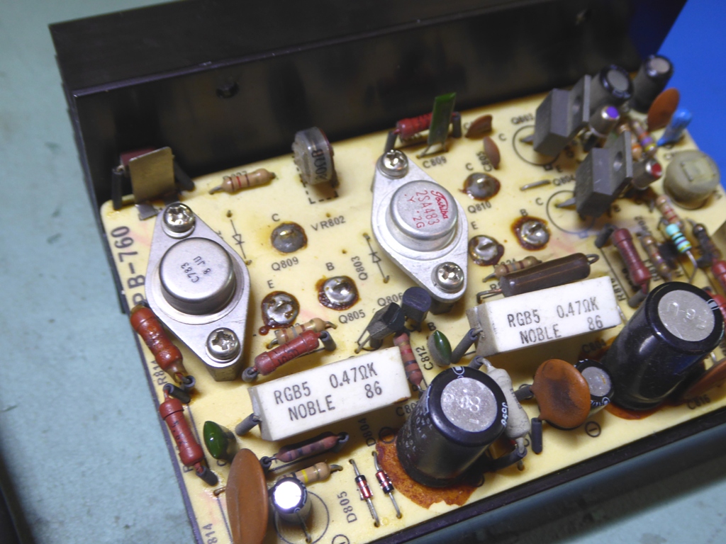


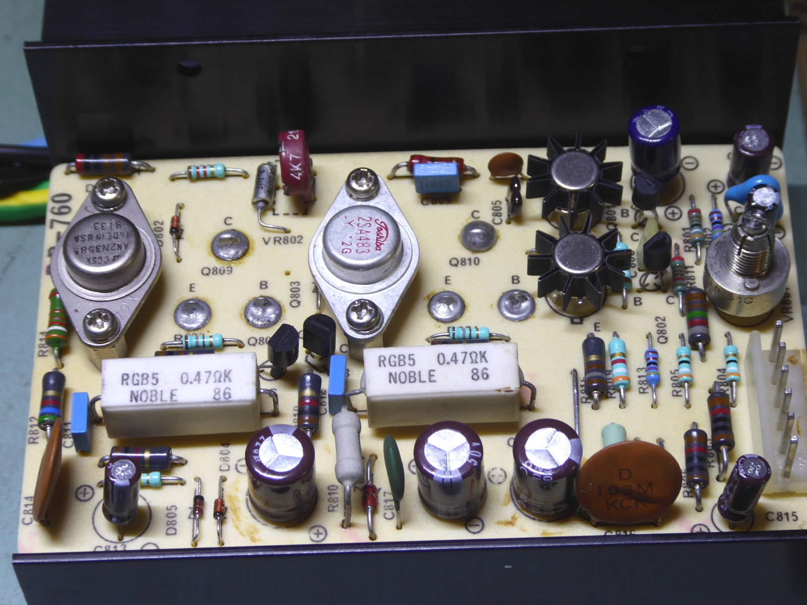
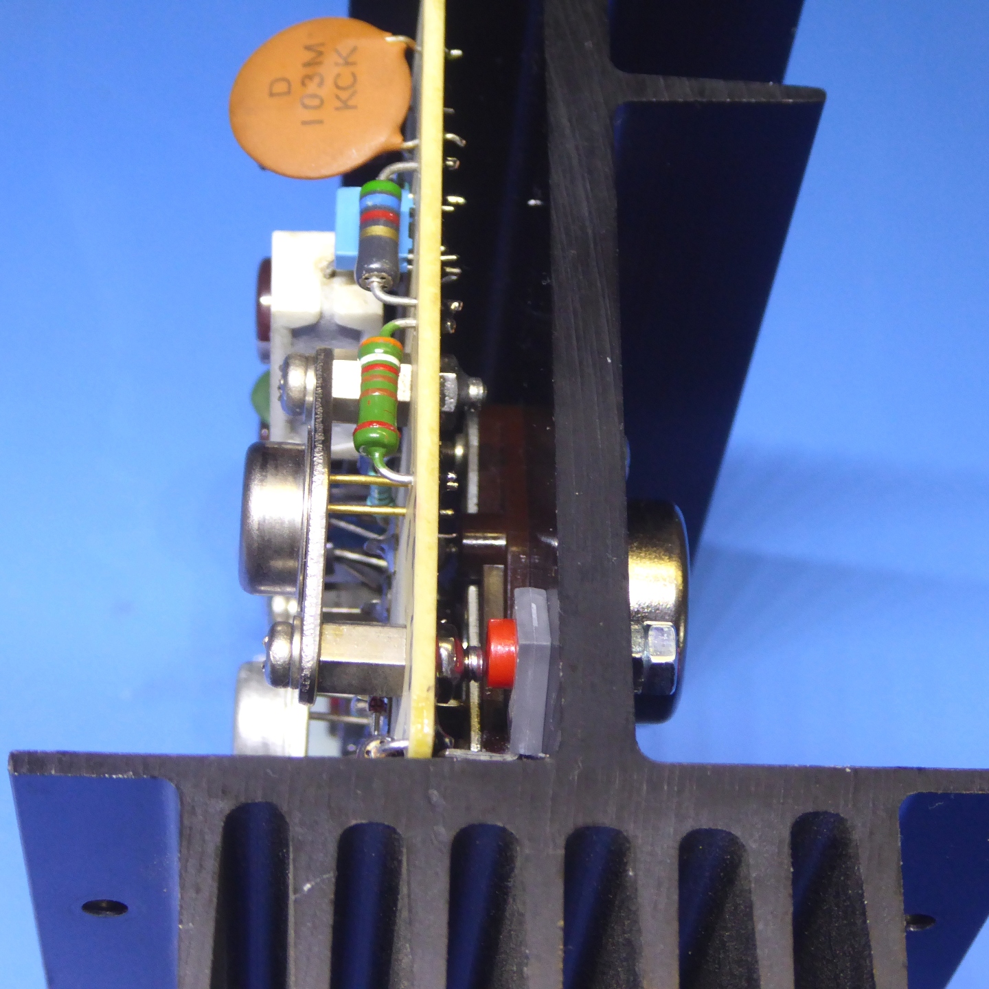
The cards were refurbished, the bias circuitry was replaced by a "vbe multiplier" circuit, employing a BD329 TO126 transistor.
The unknown-brand C783 transistor was replaced by a 2N3585 one.
Notice the VBE multiplier BD329 transistor between the card and the heatsink on the mostright picture, it is mounted using a nylon bolt.
Although the big TO-3 power transistors were still good, I decided to mount MJ15001 and MJ15002 ones, because the high amount of power the receiver can deliver.



RIAA input and microphone input card PB755
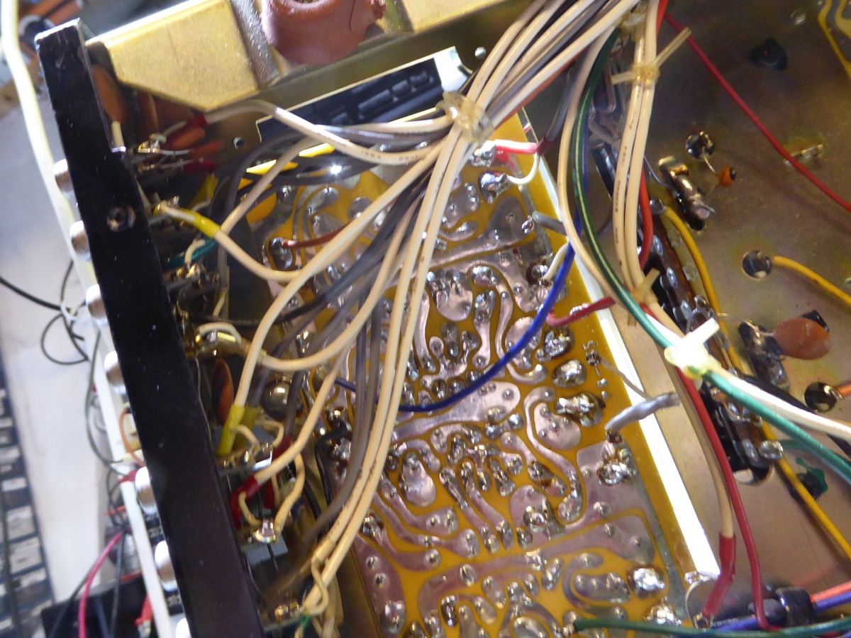
This card was not easy to remove, as cables did obstructit. I tested it on the bench, the plan was to see if there was any distortion and whether renewal would be beneficial
Right away, also here distortion figures were not the same between channels, and it was decided to just refurbish and test the transistors later.


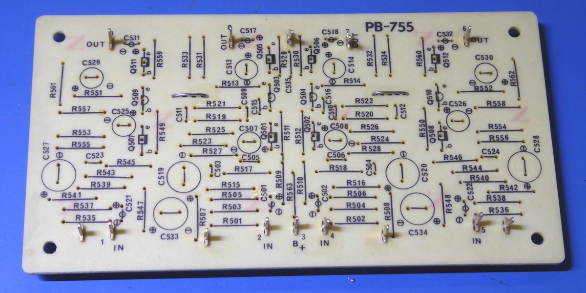

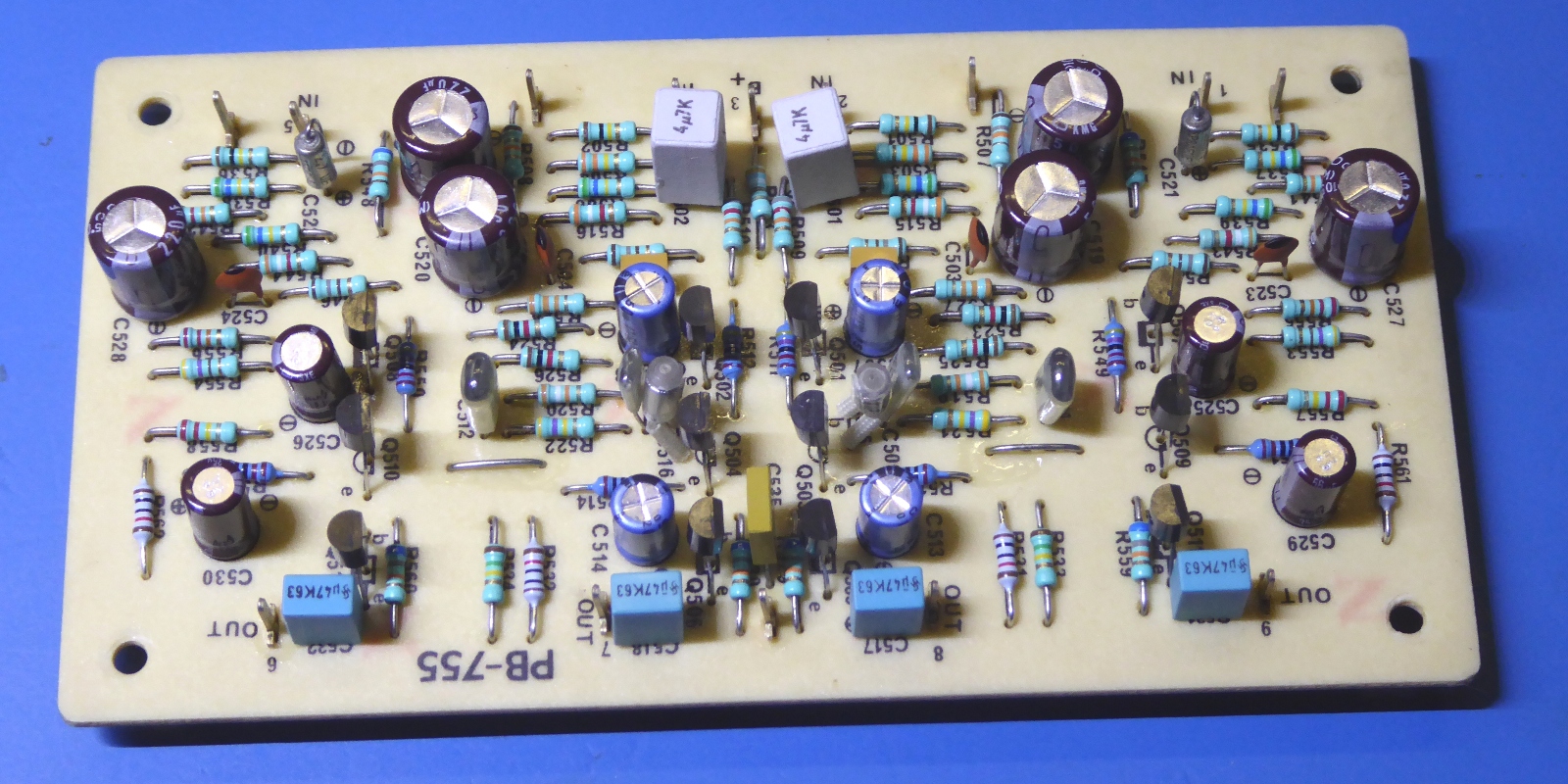
The refurbished card. Of course, no more noisy carbon resistors...

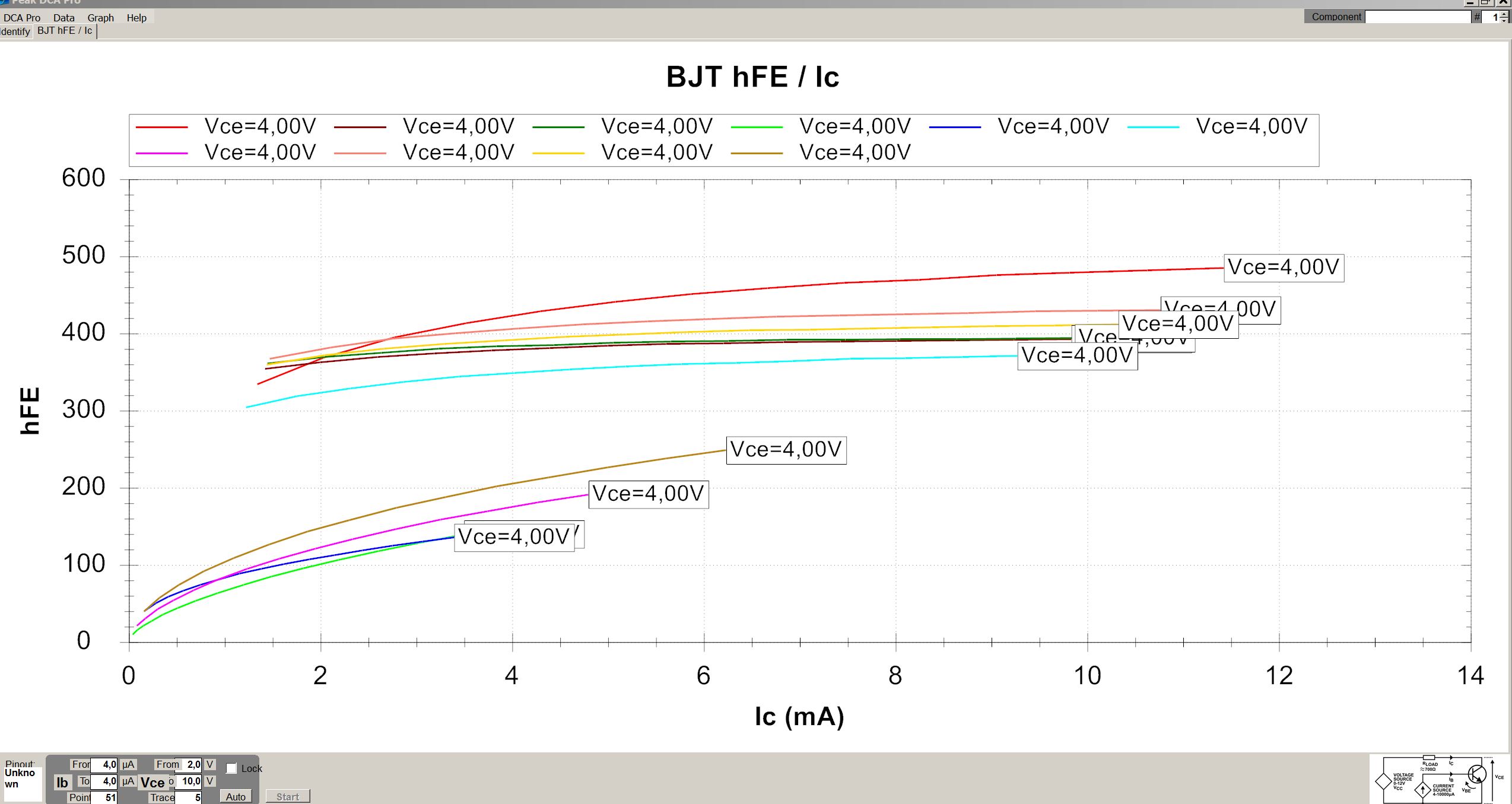
Together with some from other boards, a total of sixteen 2SC1345 transistors were tested.
Four of them appeared seriously deteriorated, as can be concluded from the HFE graph of ten of those, including the four bad ones, below.
Whereas the input signal transistors of the RIAA equalizer are set to a very low collector current, having a very low HFE one in these position would definately compromise the circuit very much, as HFE was almost gone at very low currents.
On the Audiokarma audio forum, this Hitachi 2SC1345 is on some "always replace" list. The bad behavior seems to correlate with the specific transistor package of it.


The PB756 tone control / pre amplifier.

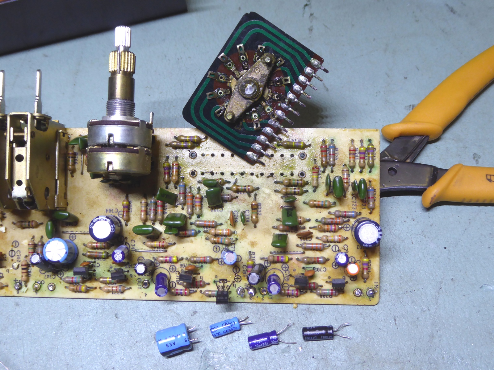
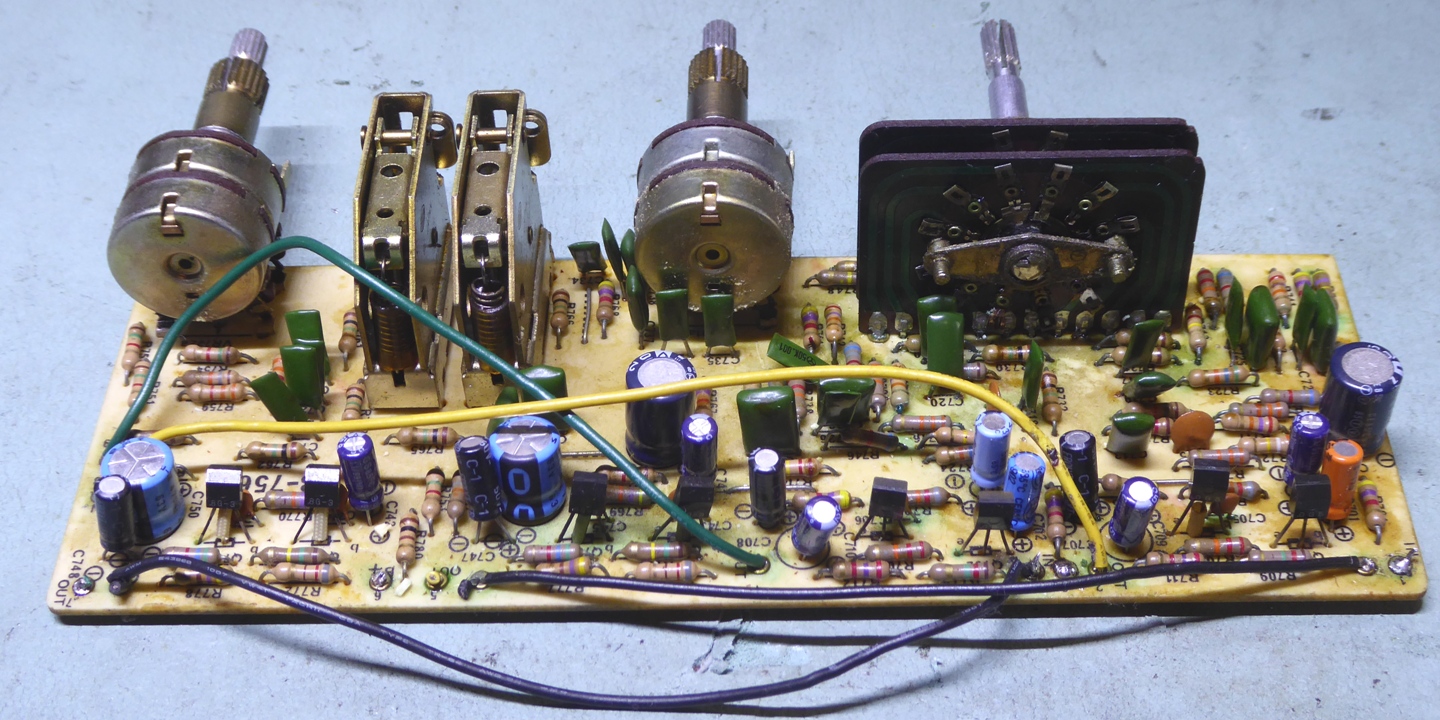
This card was rather dirty, capacitors did leak and attacked leads of other components.


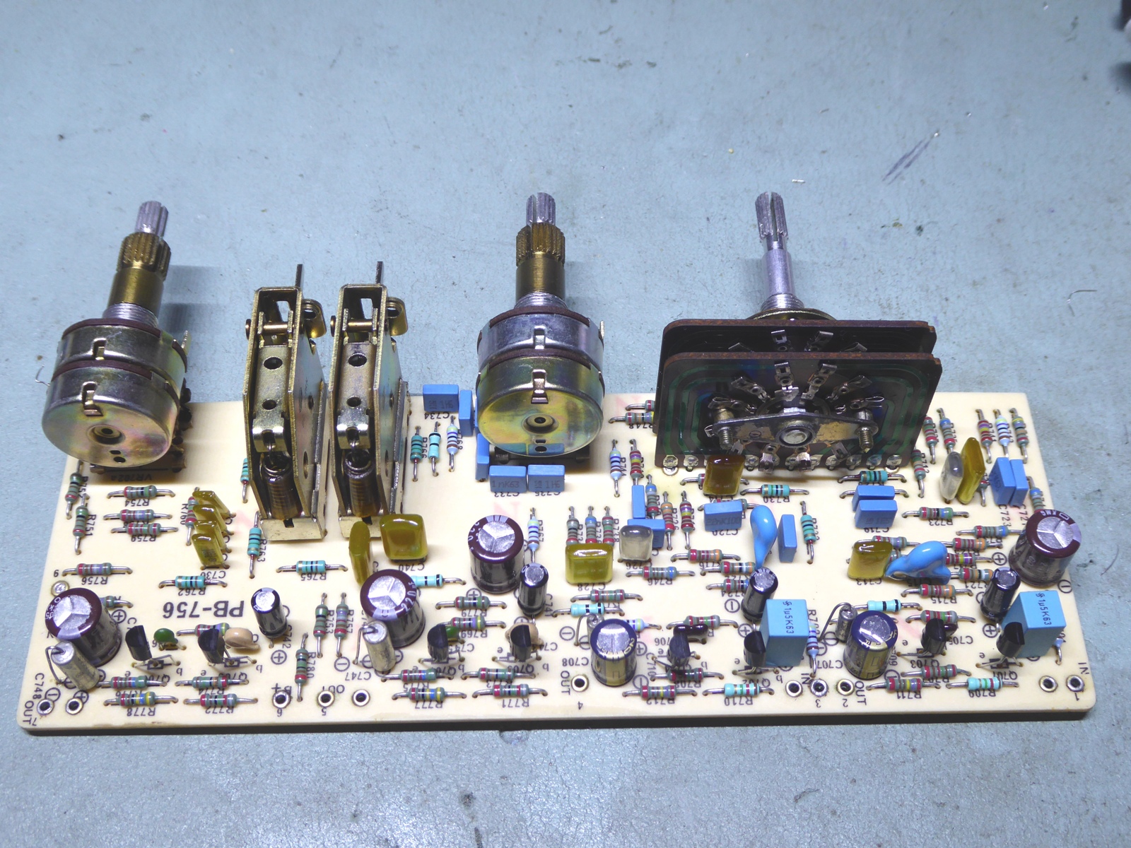
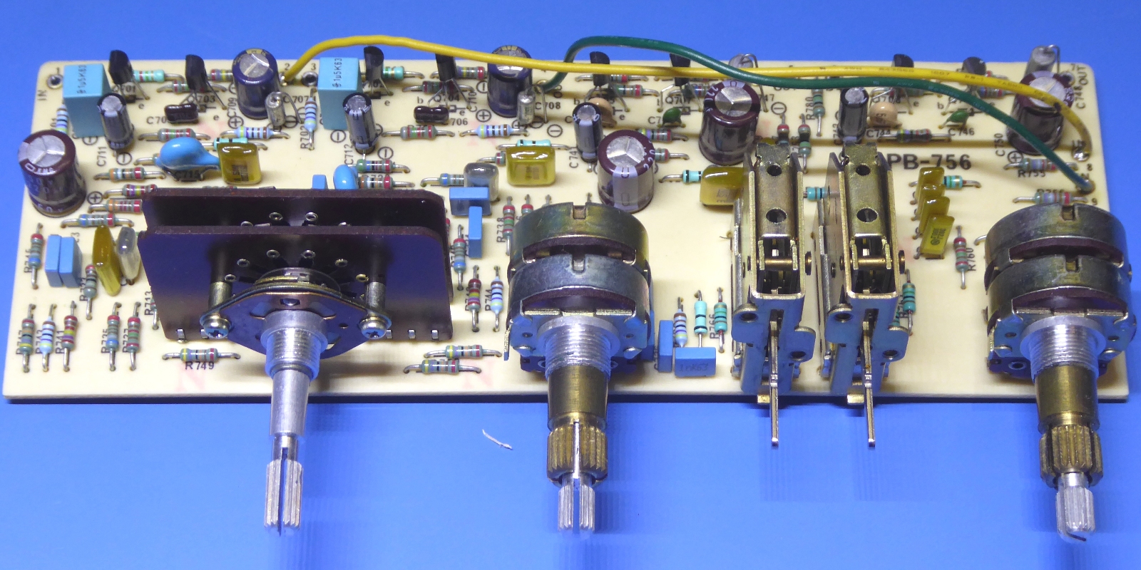
Refurbished card using top notch parts.



The mike mixer PB759 card.
This one was restuffed, also.

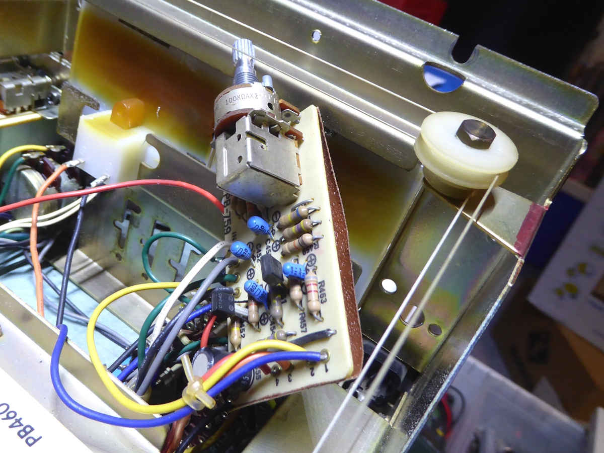

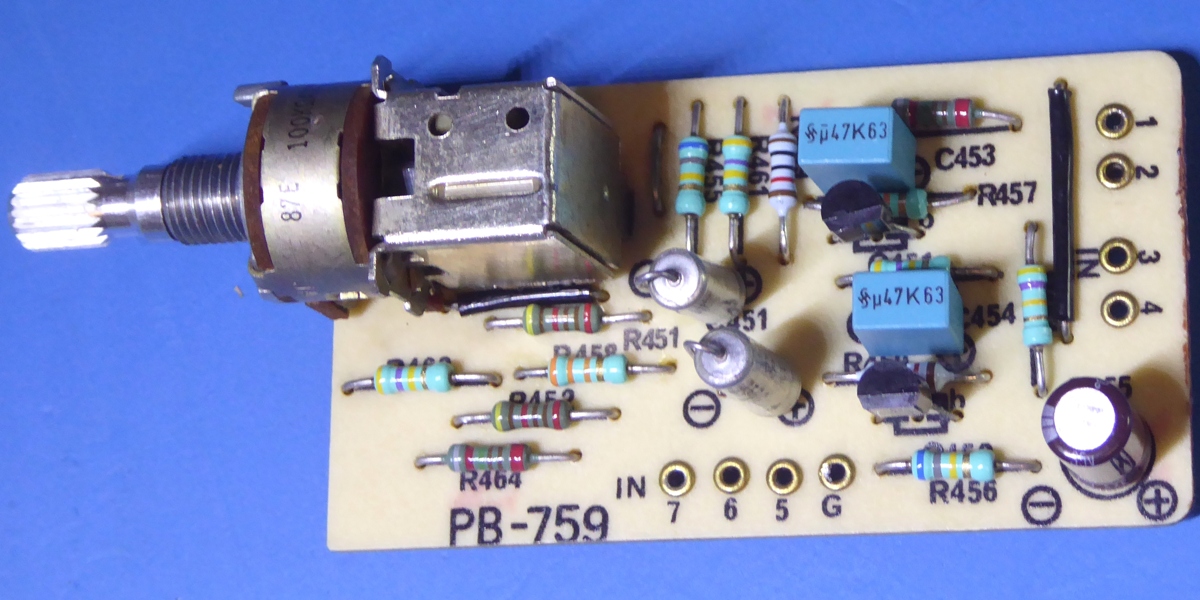


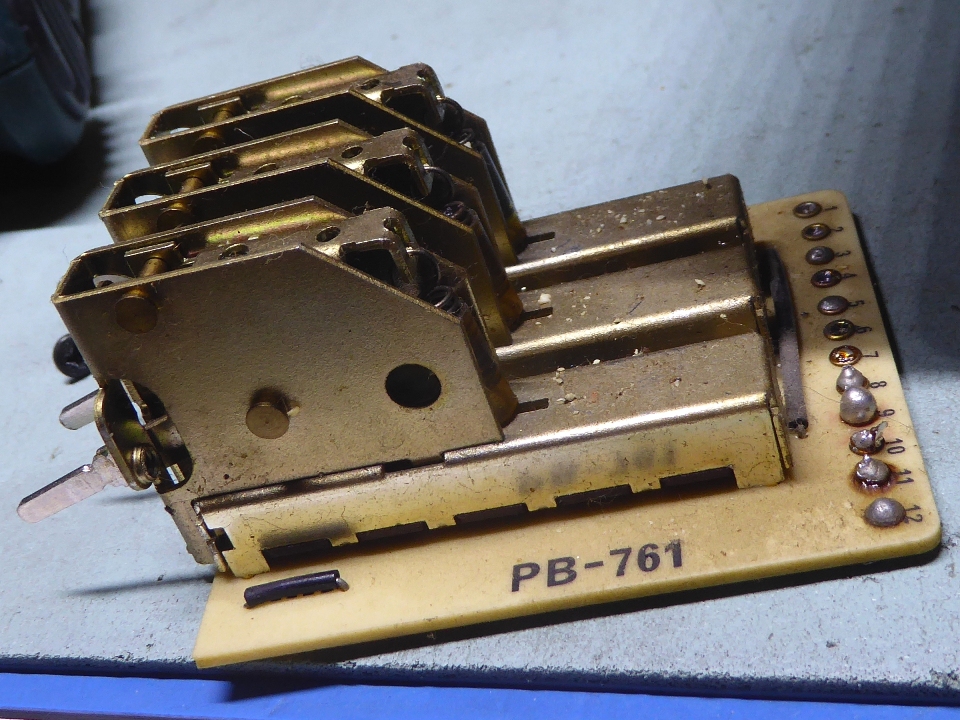
The various switching, PB204 and PB761 cards.
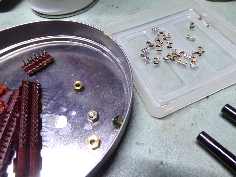
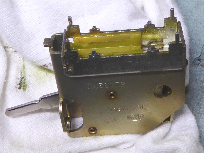
All pushbutton switches were taken apart, cleaned, and remounted.
As usual, the tiny spring contacts behave like fleas, trying to escape.





The Tuner related circuits.

The FM tuner front end was untouched, the AM tuner did had its few electrolytic capacitors replaced, and the little AM moise filter pcb carrying a slider switch was left alone.

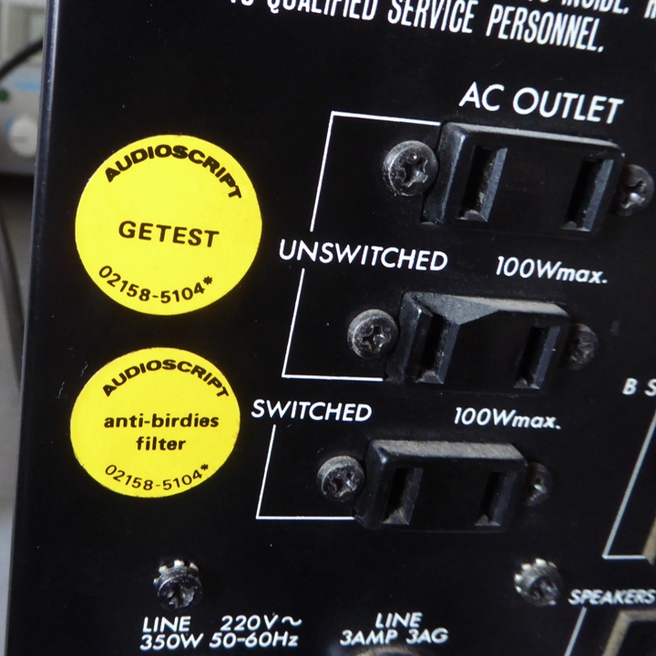
The Luxman importing company "Audioscript", well-known for their service (and attitude towards the FM quality supplied by the cable companies etc, as well, making them well respected by most techs ;-) ) , used to test evey single Luxman device, and (but?) they also had an urge to modify things as they thought appropriate.
Apparently they decided an "anti-birdie" filter was needed.

The FM IF strip, card PB353 was totally recapped. It also has its trimming potentiometers replaced.
By using the jumper I installed, I checked whether there was an audible difference tuning adjacent stations using the "anti-birdie"filter or not, but I could not hear any difference leading to a decision whether it is useful, or not......
The stereo indicator LED was replaced by a high-brightness type, earlier it was hardly visible.
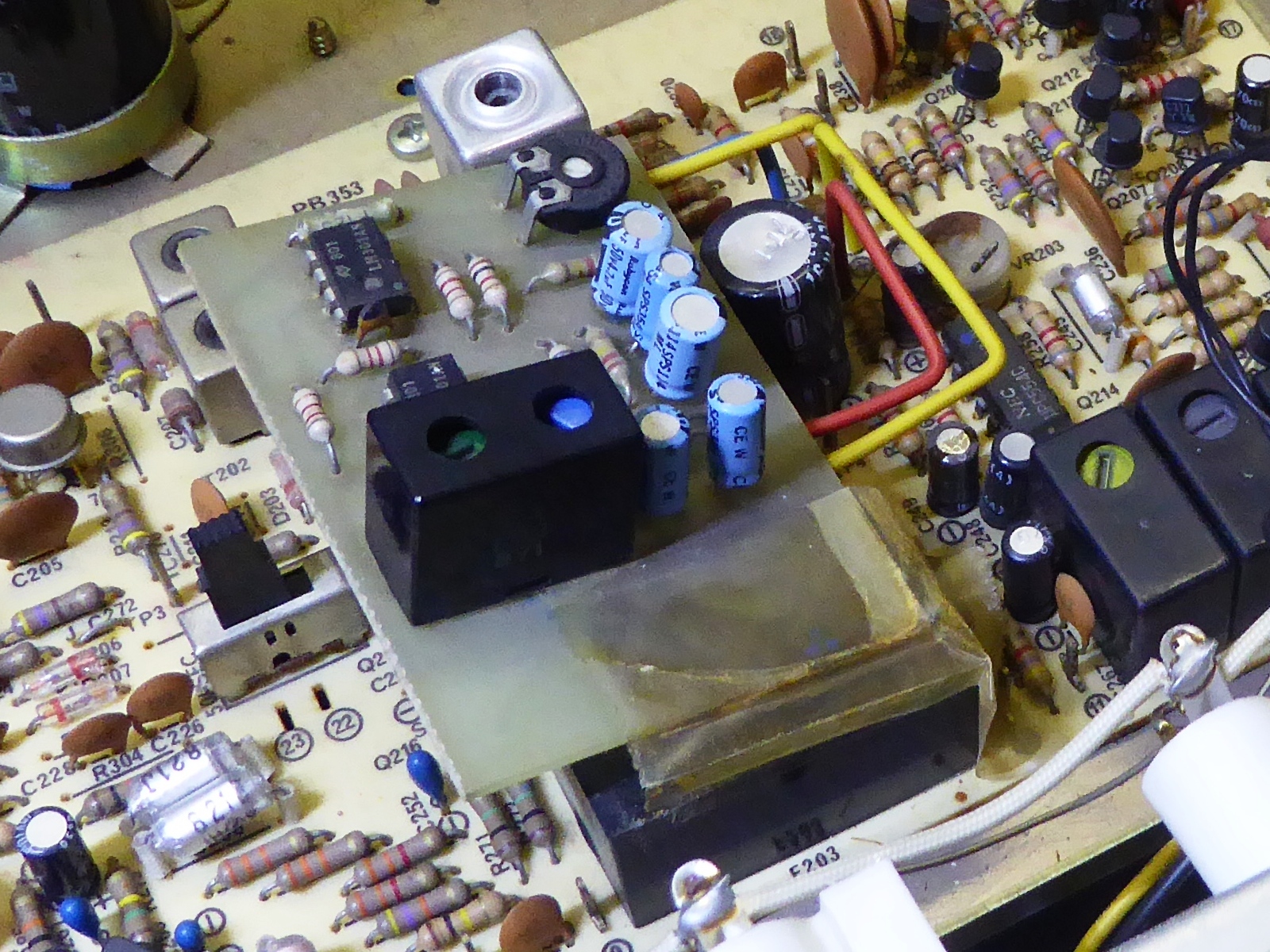


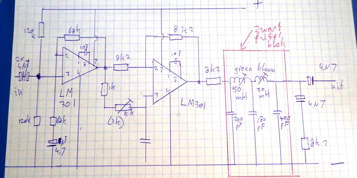
The anti-birdie filter was recapped, I made it jumper-selectable, I also put new resistors and op-amps on it, and it was relocated.
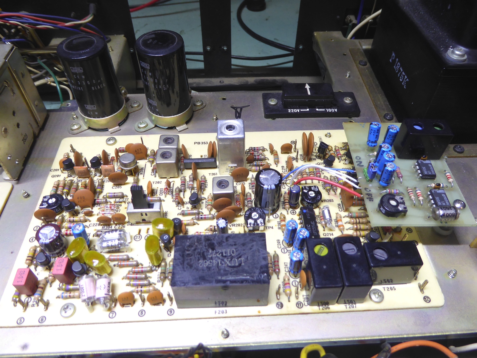
The refurbished card including the anti-birdy filter, which is technically in series with the stereo decoder chip input:


The schematic of the anti-birdie filter:
At the left, both small electrolytics making one bipolar one, were reversed.
From "in between them" the jumper can be attached in case the signal is wanted to be routed directly back to the decoder chip, as it was originally.


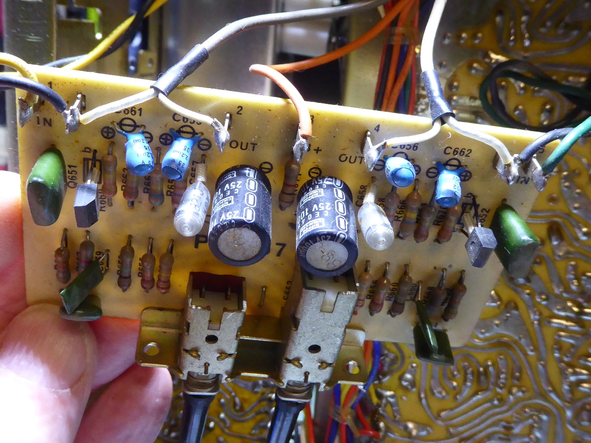
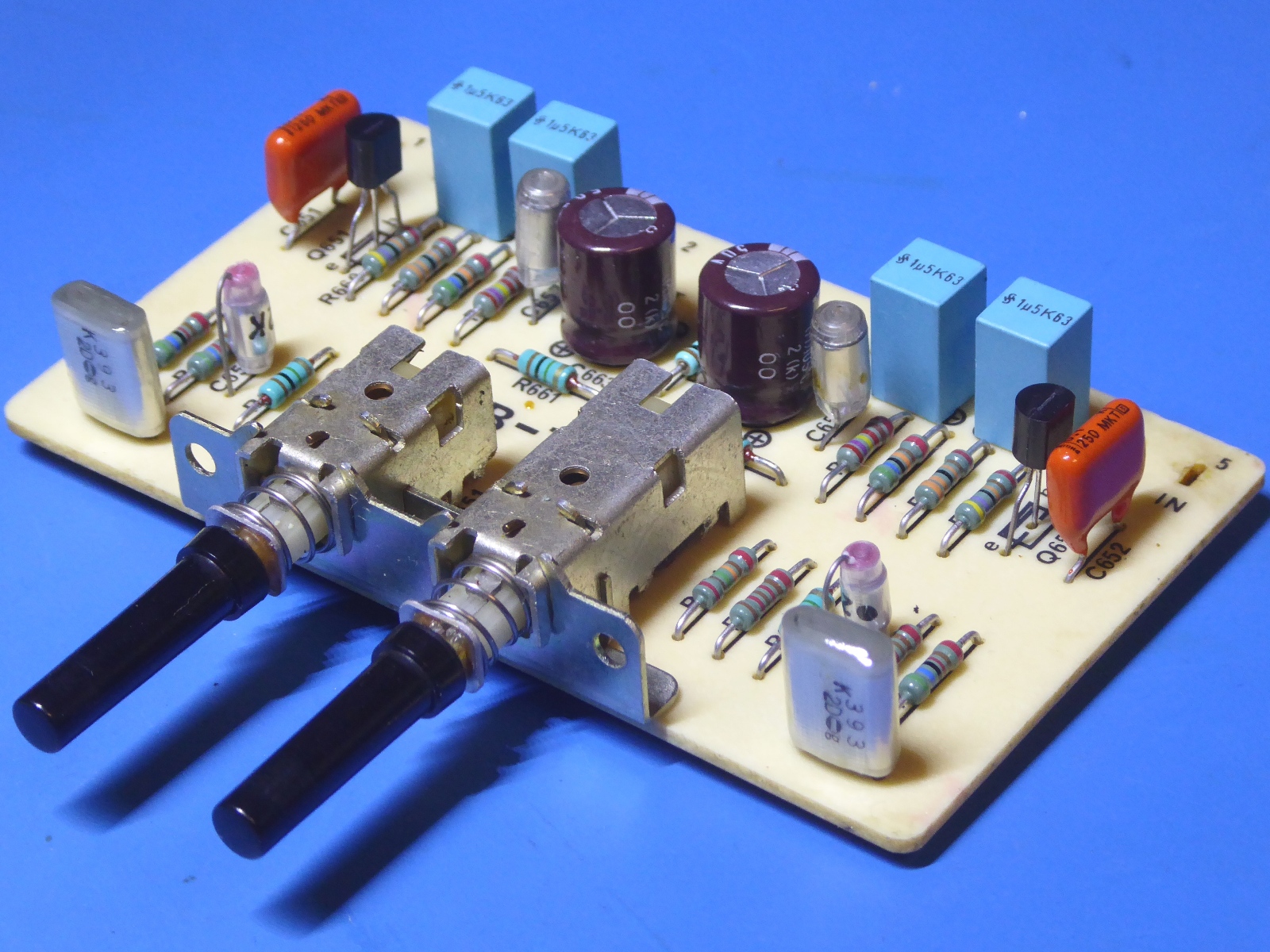
The filter board PB757 card.
This one was restuffed, also.




The receiver backlighting.

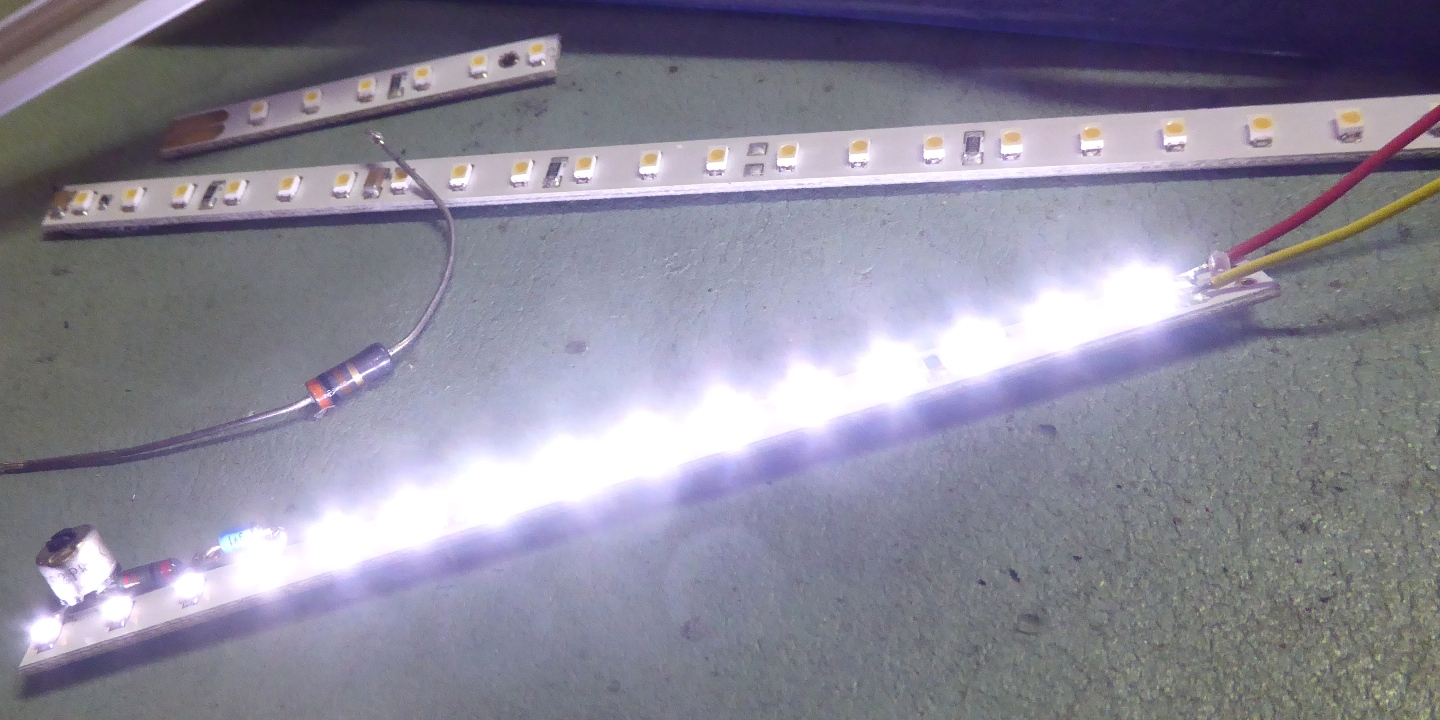
As the tuner meters are severely compromised/discolored due to lamp heating, it was decided to go for LED lighting.


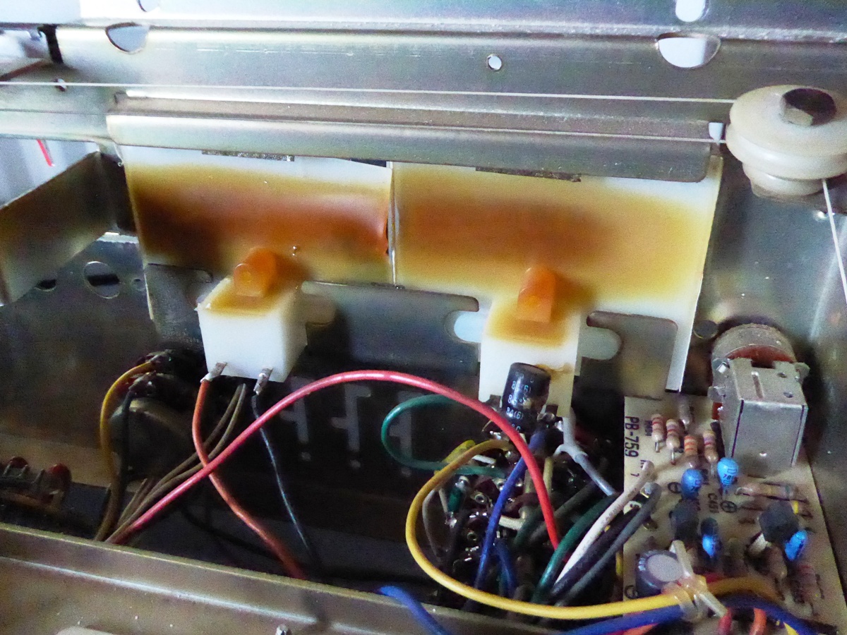


The strips consist of strings of 6 LEDs having one series resistor each string.
Because of an obstructing metal part and the need of a certain width, half a string having extra current regulating parts are on the left part of a strip piece, going behind the tuning meters.
Therefore, the three most left LED's should be tweaked for brightness after the others are set up for the wanted brightness.
As noted in the power supply section, the power is derived from a special circuit, especially created for this specific situation.
An additional trimming potentiometer is used to regulate the lighting of the tuning needle, it has a high-brightness LED now (its lamp was defective...)




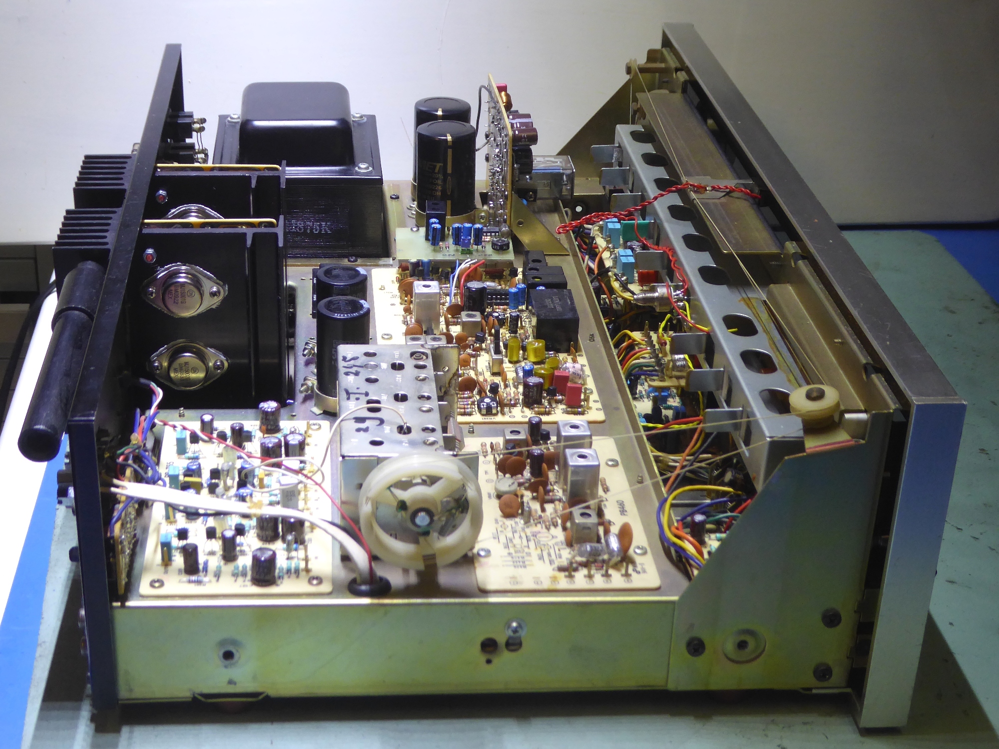


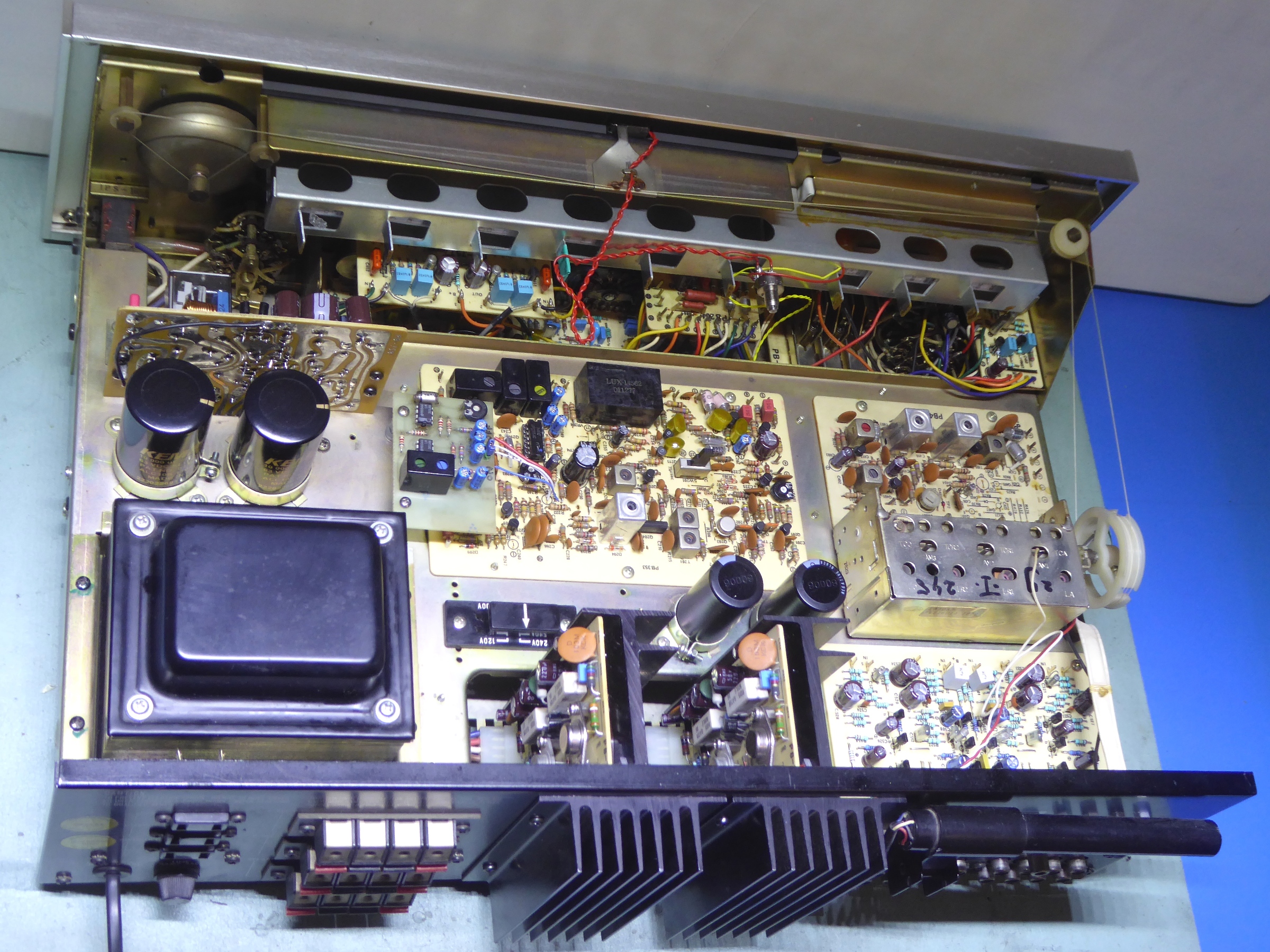


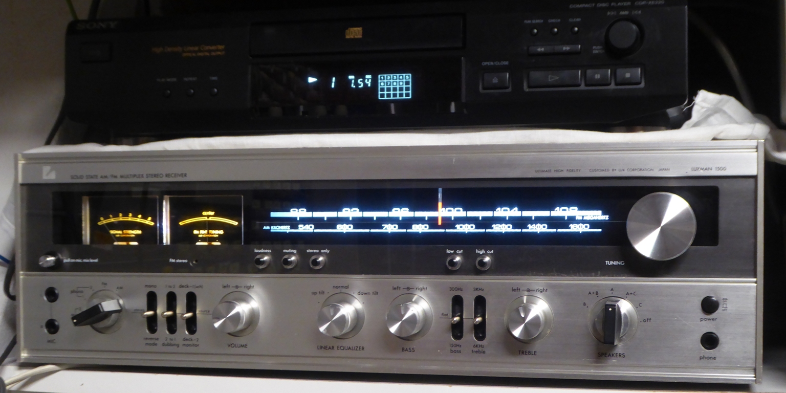


The plastic "veneer-alike" was treated using a polymer floor finish.


Ga naar Gerards page / go to Gerards page ---->>> ![]()
