Ga naar Gerards page / go to Gerards other pages ---->>> ![]()

Luxman L-309V recap / modifications 2021
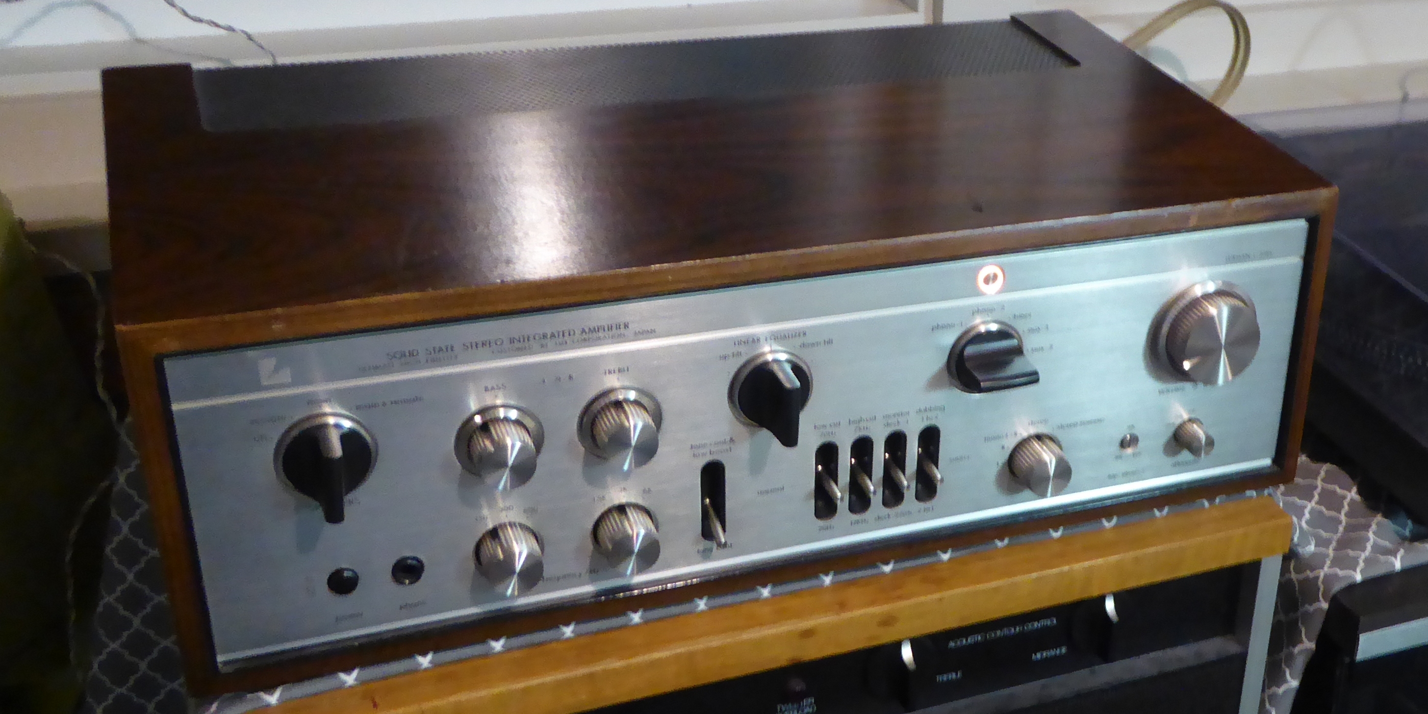

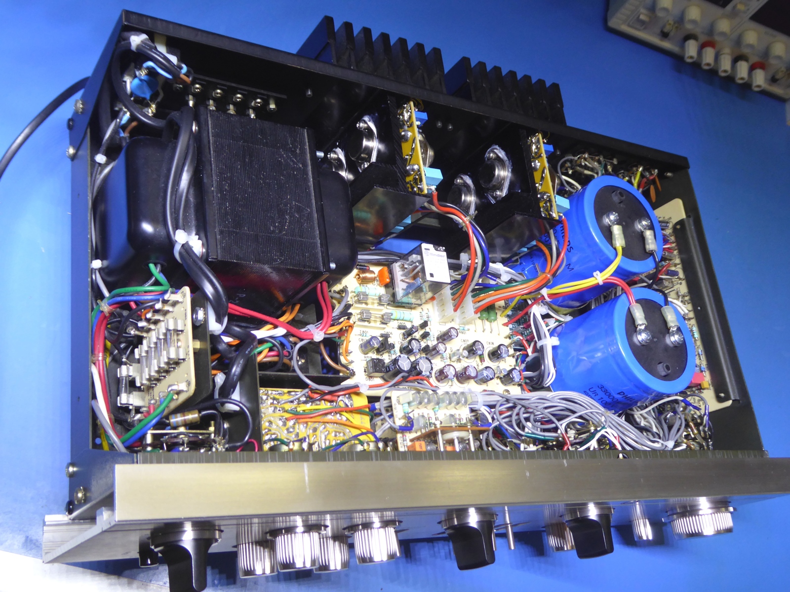

This Luxman L309V is for sale in the Netherlands, fixed price 800 Euros, cash and Local Pickup Alkmaar area as I do NOT ship.
I only answer if you provide your phone number also, see the moving mail address on my main page.
![]() Gemakshalve is deze pagina alleen in het Engels geschreven.
Gemakshalve is deze pagina alleen in het Engels geschreven.
![]() This page was written using English language only.
This page was written using English language only.

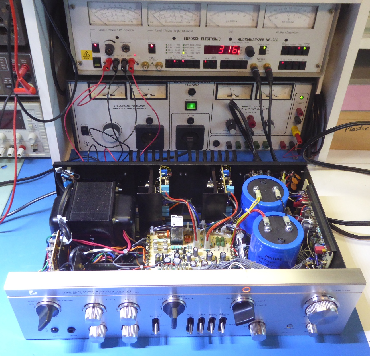
My second Luxman L309V, finished November, 2021 .

Alike my other L-309V, this amplifier was aquired as defective, this time the issue was it suddenly would put DC on one of the outputs.
This caused the protection relay to cut out.
The idea was to refurbish it to a level at least comparable to the other one done in 2014, which was still in operation but I sold it during 2023.
Also this one did get a full "recap".
Additionally, all circuit cards were unpopulated and populated using other parts, some parts of the main amplifiers and parts connected to switches and RCA connectors excluded.
The amplifier was almost totally pulled apart


![]()

Several pictures of the amplifier being taken apart
To be able to access the mains power connections, the transformer had to be removed.
Because of all circuit cards to be redone, in the end an empty chassis carrying the messy wiring harness and connected parts remained.
Noteworthy is according the L-85V manual, the transformer of the L-309V is exactly the same one.
Basically, L-85V and L-309V circuits are the same.
Therefore, the L-85V being considered as "more modern" by many, is not justified.....


![]()

The turntable pre-amplifier
One of the goals was putting a better operational amplifier in the RIAA equalizer amplifier, as the "ancient" RC4558 appeared rather noisy
The pictures show the card having its old situation, the opamp is a TO99 style "round" one.


After swiping off the components from the circuit card, it did get an adapted socket for a DIL opamp.
The pin orientation was such, adaptive "wire-wrap" wiring was needed, a commercially available adapter could not be used if wanting the orientation of the chip in line with the circuit card.


As no service manual is available, the PB1022 board was compared to the circuits used in the Luxman L-85V and Luxman L-309
Therefore, component number markings were crossreferenced.


Refurbished circuit PB1022 (picture is without opamp).
The new opamp in use is an Burr-brown OPA2604. A Signetics NE5532 was tried also, but this one gives a nasty spike powering up (in this particular Luxman circuit arrangement). Although one will not hear this as the spike is long gone when the protection relay engages, it is best to keep such things out of the amp. Apart from that the 2604 is supposed to be better.
At least, I was glad using the IC socket, instead of directly soldering in a 5532 and find out about this issue by testing the circuit on the bench first,before mounting the card.


Splan drawing of the circuit card RIAA part.


![]()


The main amplifier modules.
The main amplifiers both were repaired before.
A very funny conclusion is the technician repairing it, apparently had the same component preferences and alike stock I have, myself! Panasonic electrolytics, Metal can tantalums, and Philips green metal film resistors.
Still, the repairs were not "good enough" and the fact blown transistors in these modules cause so much collateral damage, possibly all transistors except the "current source" ones and all parts possibly compromised BY the way a module failed should be replaced.
As there is no part by part exchange possible because reassemble is needed for testing, just replacing the obviously defective parts and call it a day is NOT the way to go with these modules!

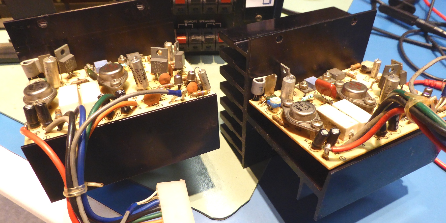


Nevertheless, one of the modules is supposed to be not okay, and the assumption was one of the smaller transistors to be the culprit.
The chance was taken, all components were replaced, with the exception of the TO-66 driver transistors and the current source transistors.


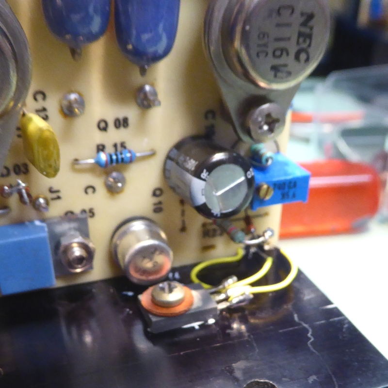
After the refurbishment, it was concluded the bias sensing transistors were not attached firmly.
Over time, those sitting on the pcb pressing against the heatsink only attached with heat compound, can detach from it, it could even be a risk factor as the amp module can not track the temperature properly.
It was decided, to drill a hole and attach a BD329 TO-126 style transistor on each module. (Although simply glue them would also have worked, but this is not the way I like it.)
The big power transistors on the heatsinks are replaced by MJ15024 and MJ15025 ones.



![]()


The equalizer filter switch.
Measuring at the rotary switch it appeared to have up to 20 ohms contact resistance at certain switch settings.
Therefore, also this one was totally refurbished. One pin broke during taking the switch off.
The switch was considered too vulnerable to take apart.


The switch was cleaned using contact spray, soaked in water and soap, soaked in IPA, blown dry using pressed air and sprayed using lubricant.
Hopefully, it will stay OK. The pin was fixed and all board components have been replaced.
This circuit card PB642 is the same as in the L-85V

![]()


The tone control board.
This board is marked PB777. The L309 parts list suggests it has this card, however, its schematic says PB727.
The difference seems to be how power is fed, it is done through a 1k resistor.
For some odd reason, the grounds on the card are separated, one of them has a 220 µF capacitor added on the back of the card which goes to the power.


I drilled holes and now the 220 microfarad capacitor resides on top of the circuit card.

![]()


The power supply and protection board PB1024.
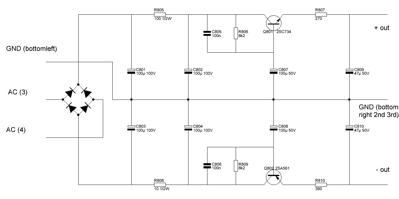
This board routes the DC power to the main amplifiers, carries the protection circuit, and provides the preamp stabilized voltages.
The fuse holders of the power board were slopy and the germanium diode was no good anymore.
The board was repopulated using other parts, and slightly modified.
The rectifier diodes were removed and they made room for the bleeder resistors, for which was no room anymore on the new big power supply smoothing capacitors.
The protection circuit differs a little from the one used for the L-85V.

 Voltage ripple suppression circuit part of board.



![]()


Switch cleaning PB-1023, the dirty circuit card.


Empty boards

Switches taken apart, the small contacts tend to act like fleas and disappear.

PB1023 board completed, again.

![]()


Various pictures.

Preamps ready, electrically suitable for test situation, unhampered by lack of the main amps and smoothing capacitors.
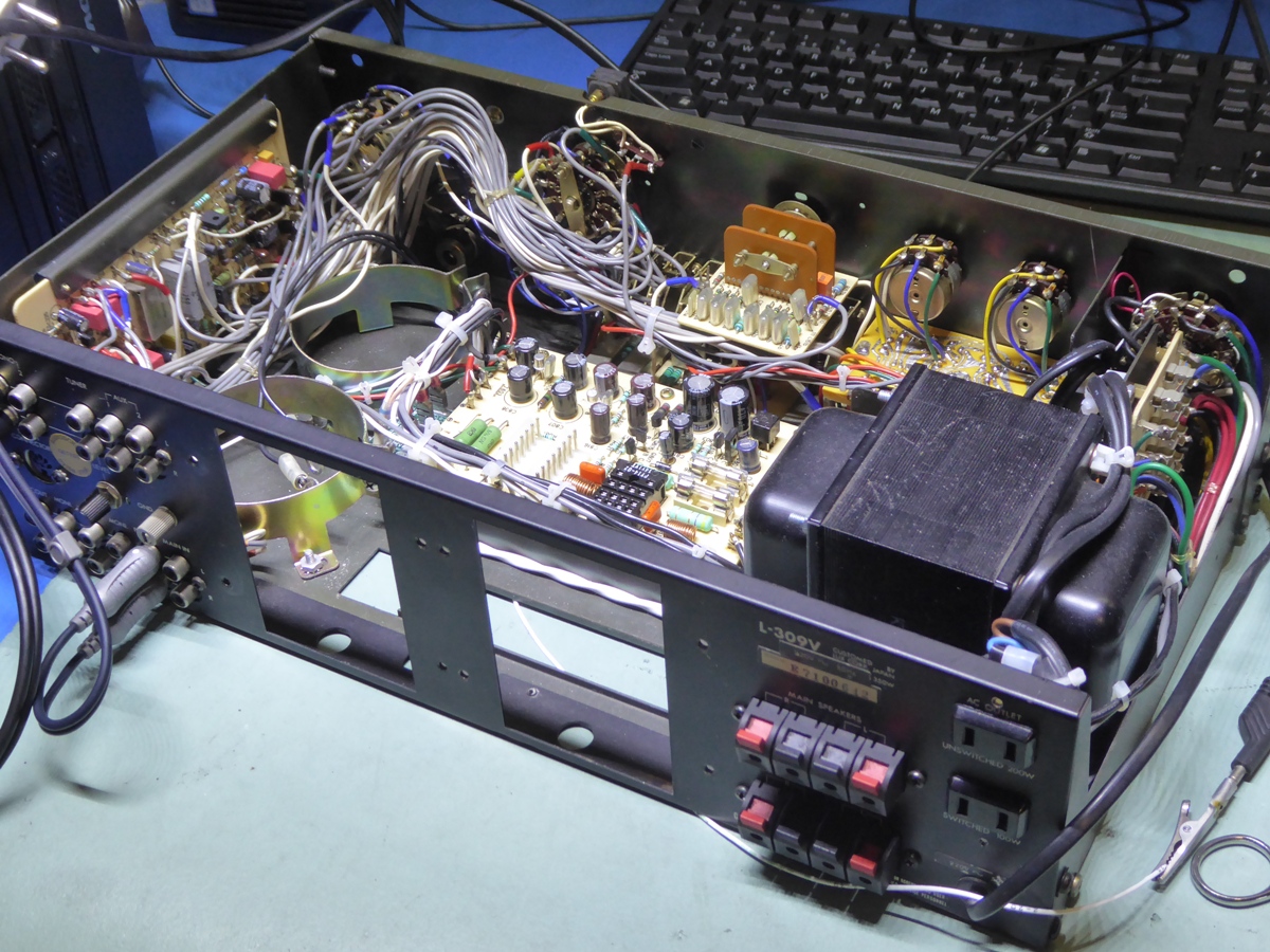


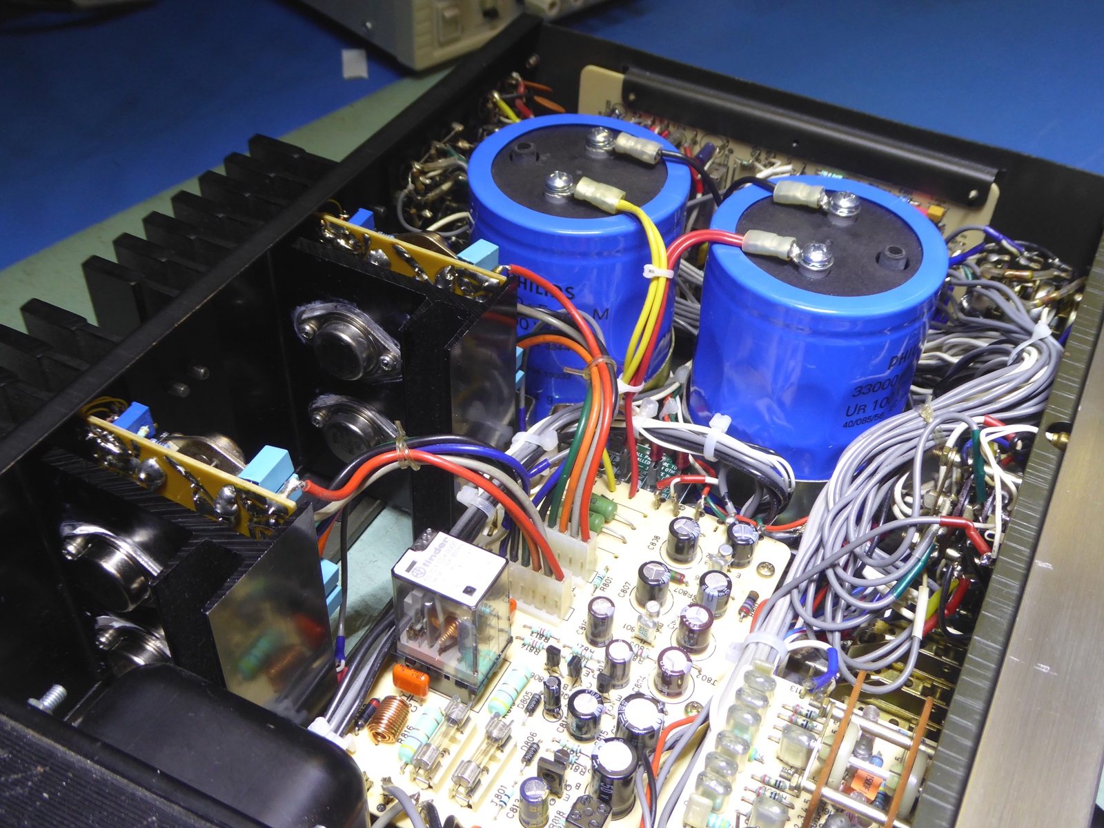
The big blue Philips capacitors are 22 years old, still much newer than the old ones, they were stored away charged. Four more of these are avail for two more restorations....Recharging around once a year they usually have over 20 Volts left of the initial charge of 100 Volts. So, extremely low leak.

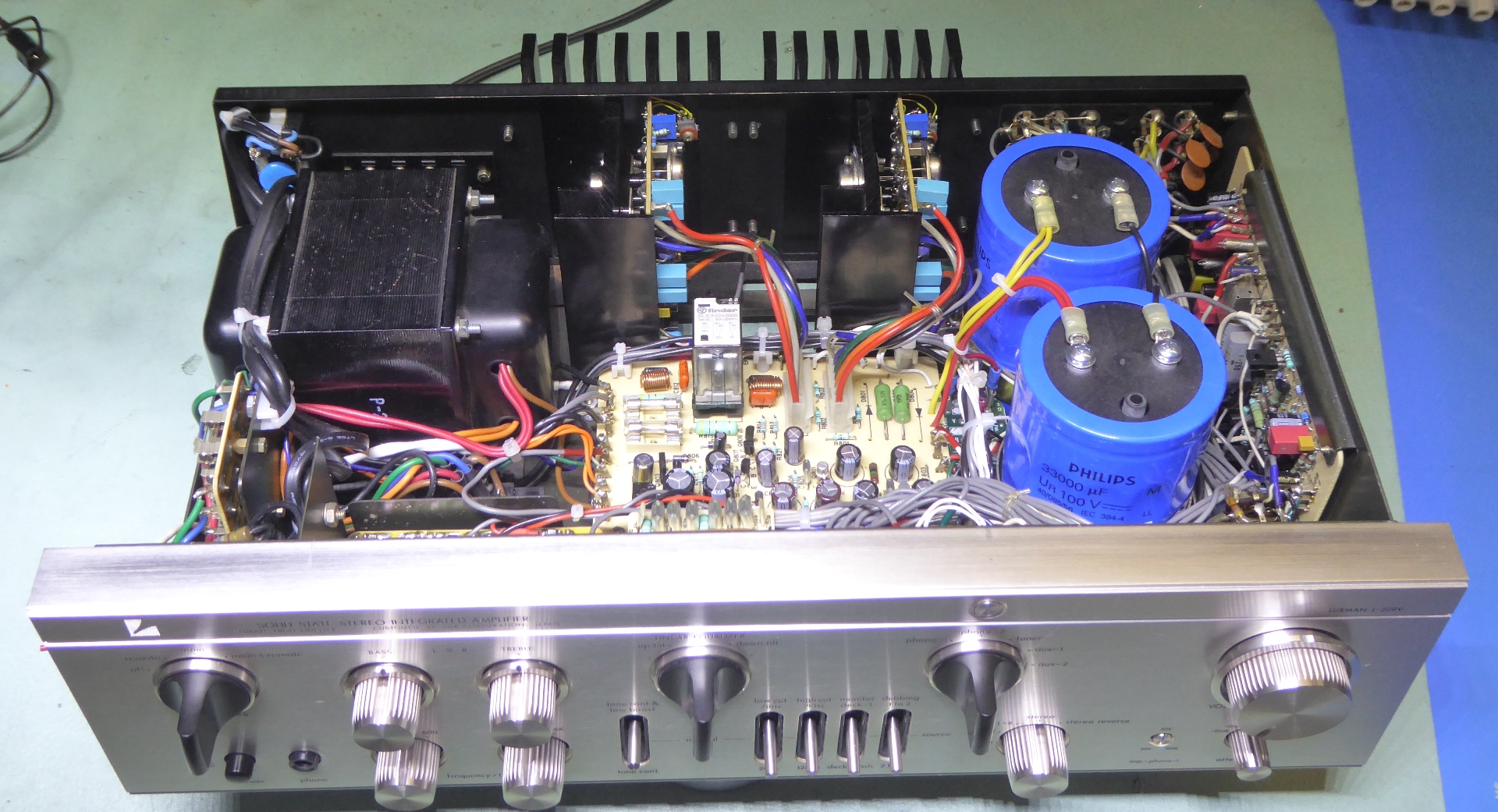
Finished, ready to challenge any other L309V or L85V ;-)


Finished


Testing 123.


![]()


See my L-308 refurbished during 2023

Ga naar Gerards page / go to Gerards other pages ---->>> ![]()
