Ga naar Gerards page / go to Gerards other pages ---->>> ![]()

Pioneer SA-8100 refurbishment / revisie, 2014.
This SA8100 was sold in 2023, paying for some nice electronic components for my next project.
Gemakshalve is deze pagina alleen in het Engels geschreven.
![]() This page is written using English language only.
This page is written using English language only.
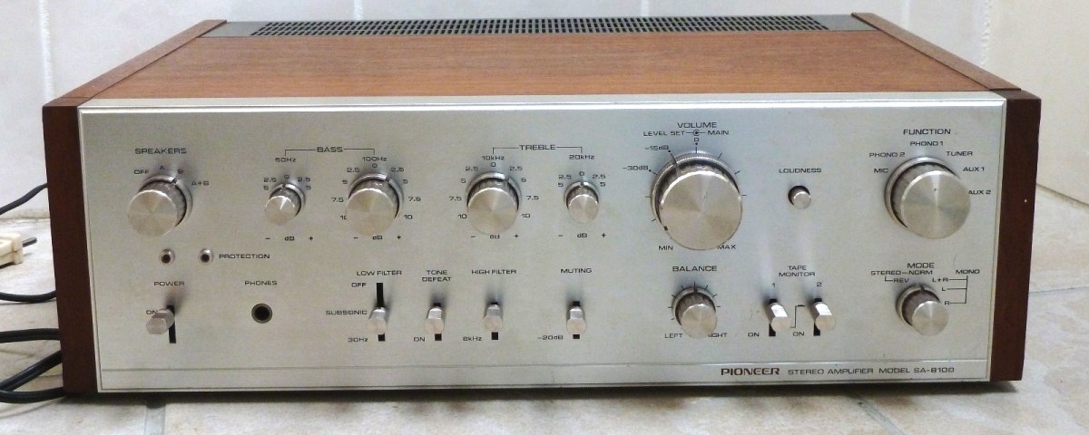
This Pioneer SA-8100 was bought from its first owner, it was said to have one channel defective.
Alike most "first owner" units, it was still looking very neat inside and outside.
Taking it apart, obvious is the nice switched tone controls. Furthermore, the volume setting has a several setting options: -15dB and -30 dB on the volume control ring, and a -20 dB mute switch.
After switching on the amplifier for the first time, while measuring at the defective channel, a capacitor did blow apart.
It was decided not troubleshoot any further and just go ahead refurbishing, as more trouble was evident now.
Further comments on this page are rather technical, more or less aimed at technicians, to share experiences. They assume people having documentation at hand, which can be downloaded from the web. Pictures on this page are generally showing an old situation first, and the new one next.
Several issues came up during the restoration of this amplifier:
1. One driver transistor was defective and one output transistor did have too low HFE in a main amplifier section.
2. 50 Volts capacitors were used on locations in the power supply where actually 50 volts average appears, which leaves no margin. It was one of these blowing up, initially.
3. While measuring pulled transistors afterwards, one 2SA628 did have much lower HFE compared to others.
4. Many small transistors did have black leg corrosion, which is considered a lurking reliability problem.
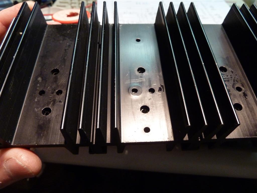
5. The heatsink was not flat, a probable cause for main amp channel to fail.
6. There was no diode protection on the relay coil, needed to protect the relay switching transistor.
7. The protection circuit was intermitting, caused by a defective transistor (not the relay switching one).
Most of the things done are shown below:

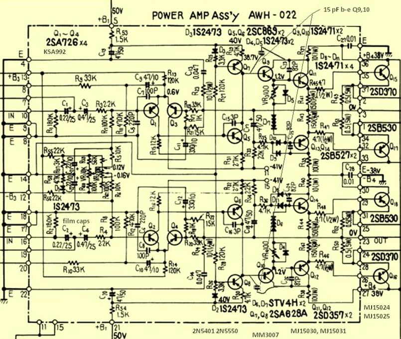
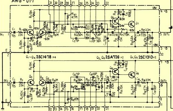
The main amplifier
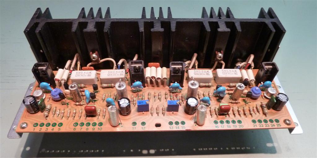
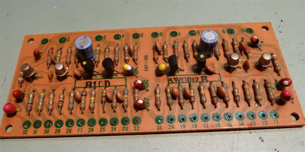
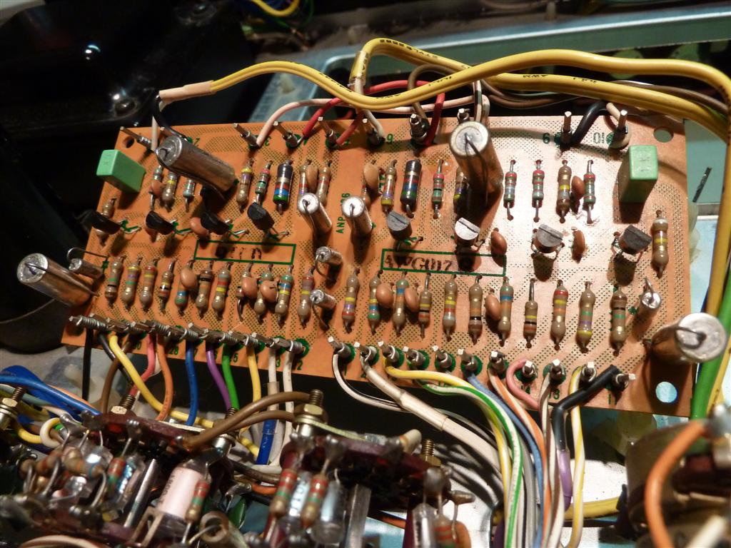
| The main amplifiers are not very accessible for repair. The plate carrying the protection board has to be removed, as it is in the way. Once removed, the circuit card is accessible. As the amplifier was already defective, a lot of parts were taken off the board, and all transistors were replaced by types, supposed to be suitable. |  |
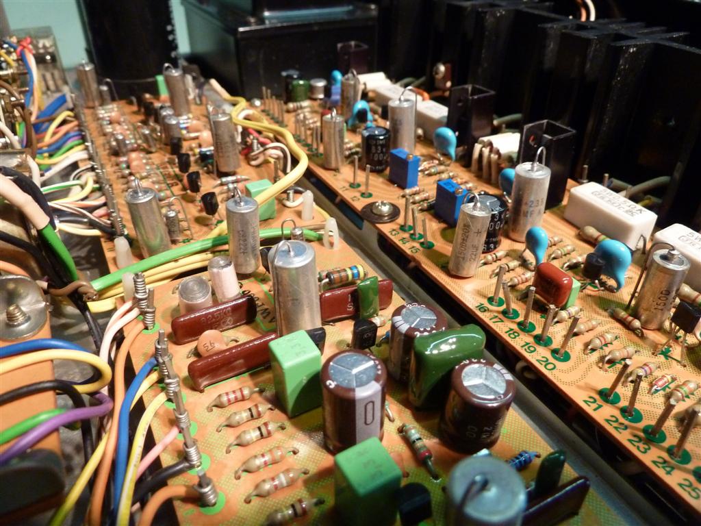
| Amplifier board having replacement components mounted. Electrolytic capacitors having metal looks are tantalums, Sprague 150D or similar. They are NOS (new old stock) but have no ageing like Aluminium electrolytics. The amplifier went into oscillation, apparently the characteristics of the new transistors did deviate too much from the old ones which have unknown characteristics. Capacitors of 15 pF value were mounted between base and collector of Q9 and Q10, getting rid of the problem.
The heatsink of the amplifier was not totally flat, one transistor was even lifted up. It is unknown, if this was leading to an overheat situation. A fil(e) and sandpaper were used to flatten the surface. See this "elevated" spot in the middle of the picture, right on the hole of a transistor mounting space. |
 |
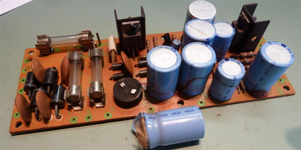
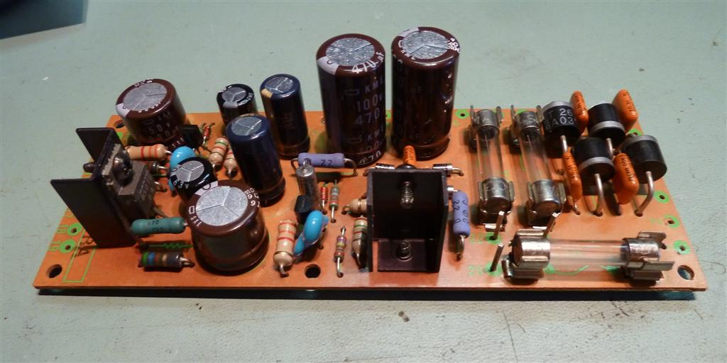
The power supply board
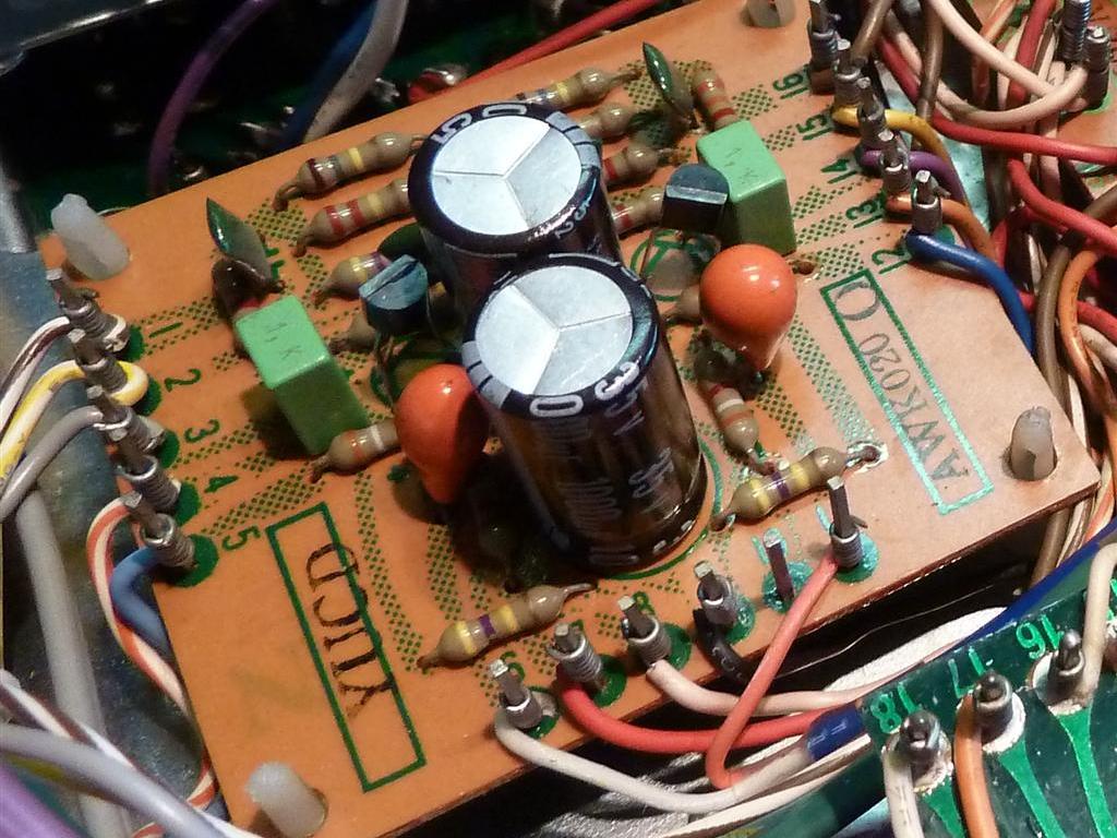
The power supply board is located at the bottom, as at most old Pioneer amplifiers. As there is not much power needed, unlike a SX838 receiver (as an example), it does not get overheated.
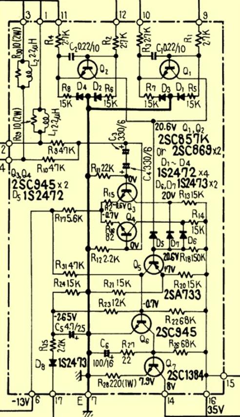
There are two zener diodes directly providing a stabilized voltage, there are two derived voltages and other voltages are derived from that depending on current through certain resistors. On the picture the blown capacitor is present.
RIAA equalizer amplifier
Transistors were replaced by BC550C, BC560C, KSC2330, capacitors were replaced, also some resistors which were supposed to be contributing to noise based on their specific circuit location.
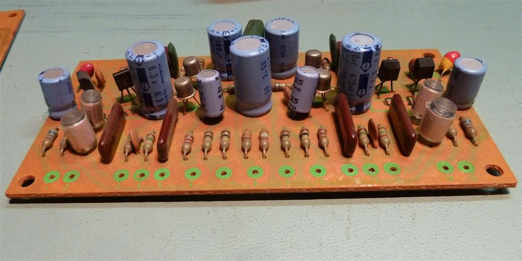
Control amplifier
The control amplifier has its capacitors replaced, some resistors were replaced for metal film ones, where they are supposed to be able to adding to the noise level.
Transistors have been replaced by BC550C / BC560C
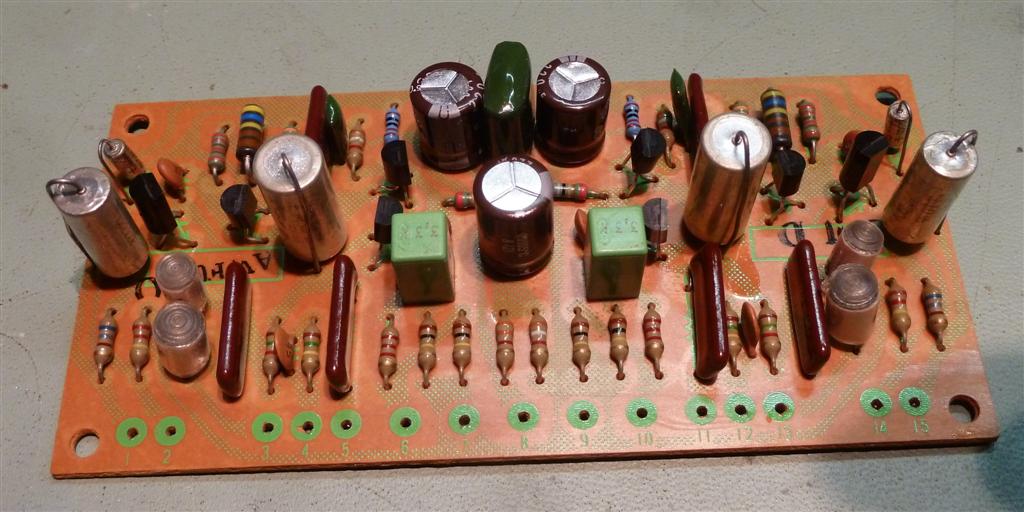
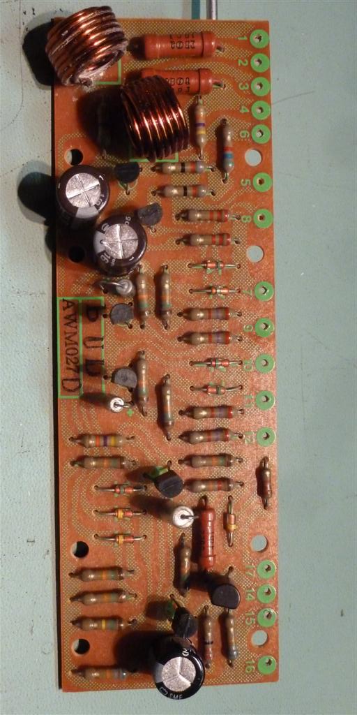
Filter amplifier, Switch circuit, protection assy.
The filter and switch circuitry is alike, having FKP inputs and known good drop shape tantalum outputs, transistor BC550C.
The protection assembly did have problems with Q4. Q1,2,3,4 are BC547b now, Q5 is a BC557b. A diode 1N4004 is mounted between 14 and 16 and the bottom of the pcb, to protect Q7 against pulses when switching off the relay.
The main capacitors were not replaced, I do not have them available.
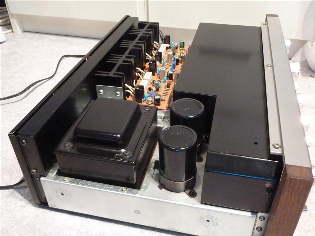
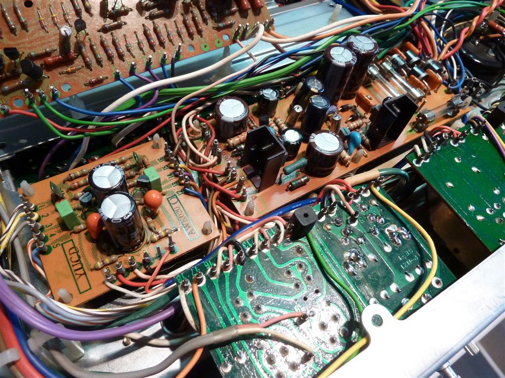
Mounted back the boards, before tyrap the cables and some more cleaning up.
Ga naar Gerards page / go to Gerards other pages ---->>> ![]()
service manual reparatie repair review schema schematic schaltkreis