Ga naar Gerards page / go to Gerards other pages ---->>> ![]()

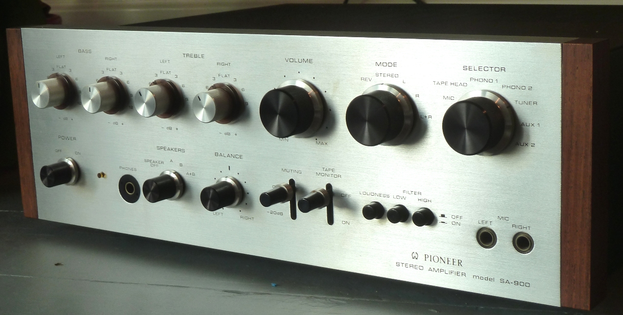
Pioneer SA-900 recap / refurbishment / revisie, 2016.
Gemakshalve is deze pagina alleen in het Engels geschreven.
![]() This page is written using English language only.
This page is written using English language only.
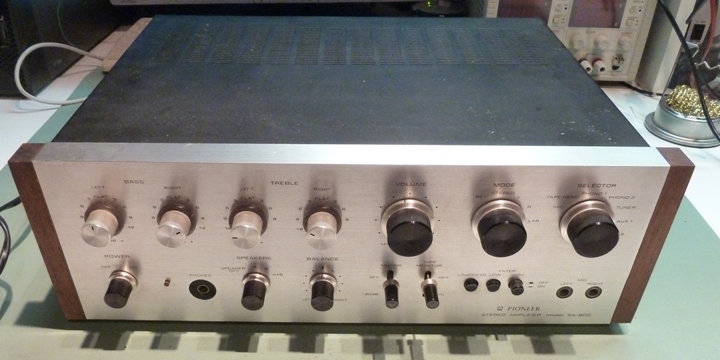
This Pioneer very nice and sturdy SA900 was bought in good shape, however one channel of the preamp did not work.
It was decided to do a quick refurbishment, using parts already at hand. It appeared that the wire wrap pins can not be unsoldered without taking off the wires, so circuit cards need to stay in the amplifier while working on it.
Further comments on this page are rather technical, more or less aimed at technicians, to share experiences. They assume people having documentation at hand, which can be downloaded from the web.

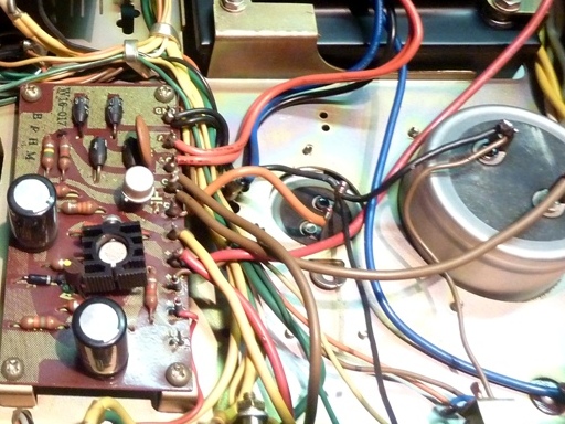
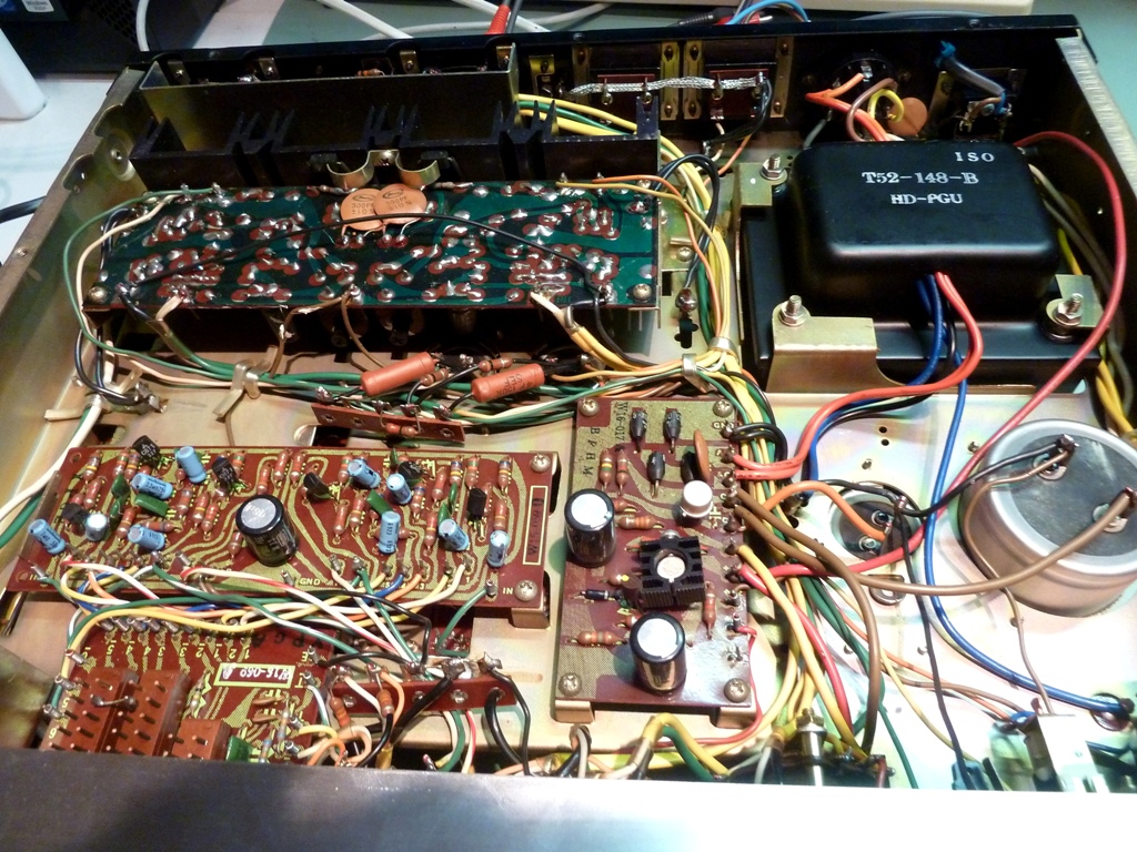
The power supply and supply board W16-017
The power supply board is located at the bottom, as found on most old Pioneer amplifiers.
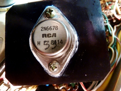
It delivers several voltages, the most intriguing part is the about 80 volts supply to the main amplifier. It passes through a TO-3 power transistor, which is not drawn as such in the schematic, not mentioned, nor is it on the parts list. It was a 2SD217, including miller-capacitor of 10 nF. The transistor was replaced by a more rugged 2N6678.
The big DC power smoothing capacitor was 2200 ”F, it is 12000 ”F, now. The smaller one adjacent to it went from 470 ”F to 3300 ”F capacitance. These parts were choosen because of the diameter size, and having them at hand. The transistor Q1 feeding the 2N6678 was replaced by a 2N3439, which is more rugged. R8 is bypassed by a 470k resistor to have a little more voltage on the preamp. Also, for protection at high currents, a diode is mounted from the 470 ”F capacitor to the 12000 ”F one, to be able to deplete the 470 one through transistor saturation, instead of through the Q1 base in case of short circuit and power off.
One more change was replacing the rectifier diodes by a 6 Amp bridge rectifier, capable of feeding the big capacitor.
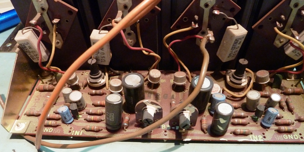
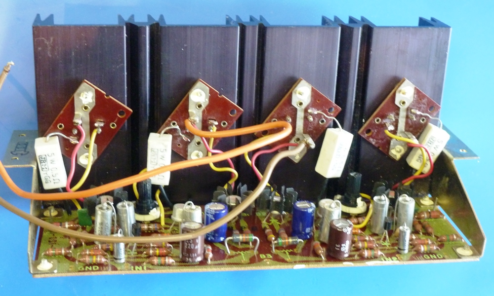
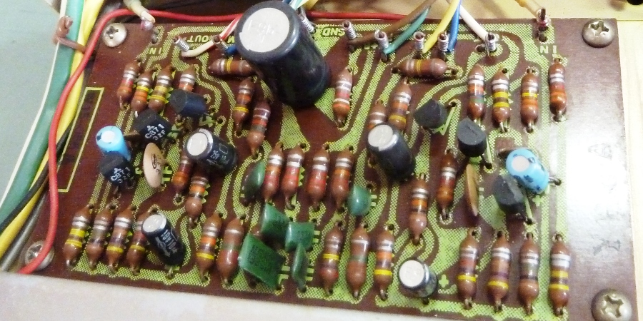
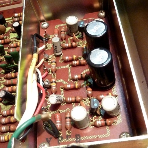
The Main power amp W23-010
The amplifier board did get other electrolytic capacitors, and the less accessible 50k potentiometers were removed. In the end, they were replaced by 100k potentiometers, as they were both turned to maximum resistance. Apart from the input transistor 2SC870 which was replaced by a KSC945, all other semiconductors stayed as is. New heat conduction paste was applied to the 2SD218 output transistors, including mica washers. The off-board output capacitors went up from 2200 ”F to 4700 ”F, again using parts scavenged from other equipment.
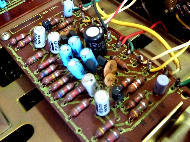
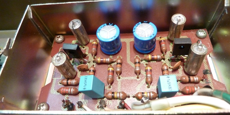
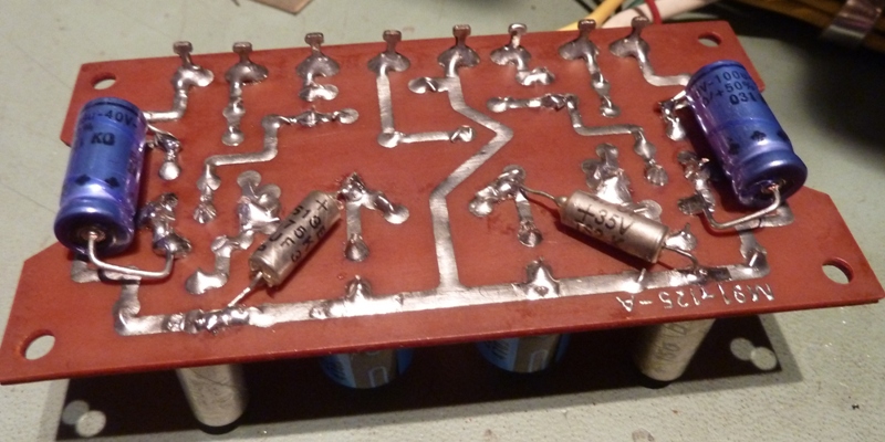
The Filter amplifier W15-059
The filter amplifier did get new KSC945 transistors. Apart from the power supply electrolytic which was replaced, a bypass ceramic capacitor was mounted underneath to eliminate possible RF, the input capacitors are film ones now, the others are Sprague 150D high quality tantalums.
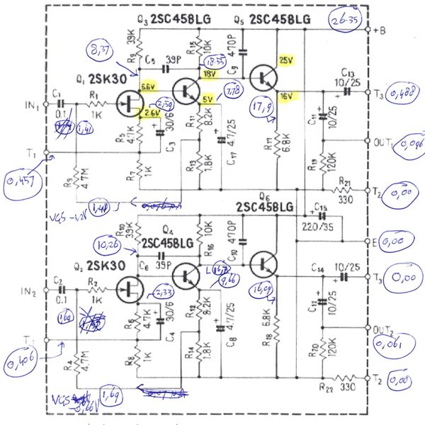
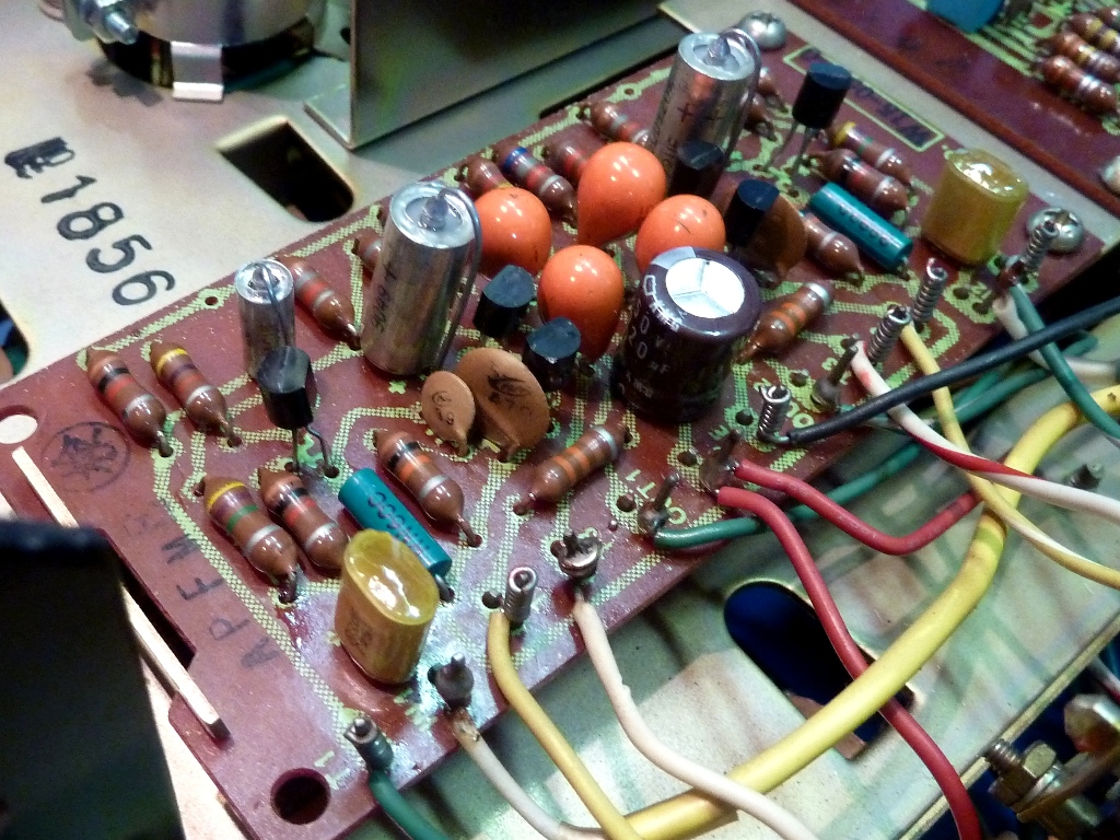
The Control amplifier W15-050
The Control Amplifier did suffer from big voltage differences, apparently because of differences between the 2SK17 FETs. Measured voltages are in the schematic. The FETs were replaced by BF245A.
The supposed-to-be 4.7/25V capacitors C7,8 were found to be 33”F 6 Volts in reality, so they carried overvoltage. The rest of the circuit card was updated also, replacing electrolytic capacitors and transistors.
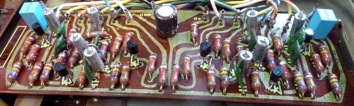
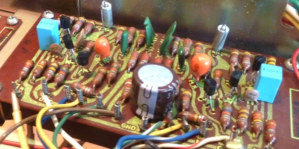
The Head amplifier (input amplifier also for MM turntable) W13-056
The Head amp did get new transistors and capacitors.
Pioneer partly used 5-ring resistors here, I presume low noise types.
The MC amp, moving coil preamplifier
The moving coil amplifier consists of a single transistor common base circuit. Assuming low base resistance is mandatory, the old 2SC871 transistors were replaced by good HFE medium power transistors, KSC2690Y. Extra 100”F caps are paralleled on the bottom of the circuit card, as well as low impedance bypass power supply capacitors. It is a bit overkill and 'recap paranoia', it does no harm. Now, a MC equipped turntable is not available, so this circuit remains untested.
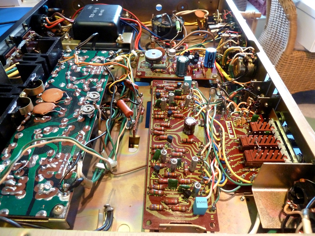
The amplifier bottom side, before the update
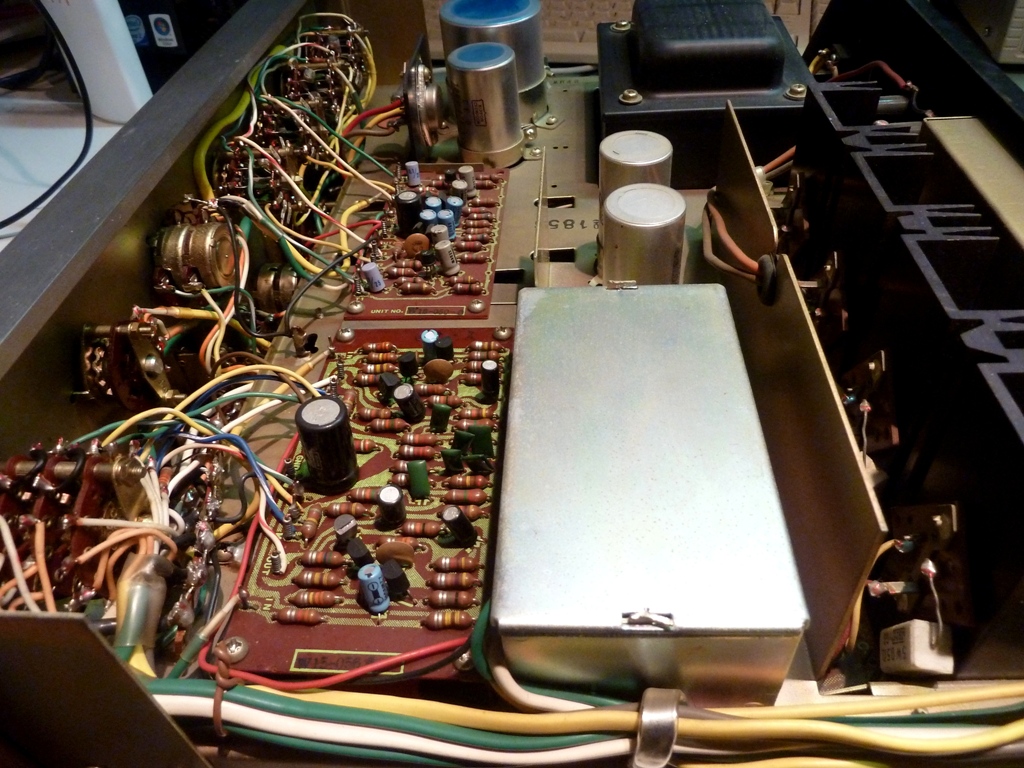
Bottom side, after the update
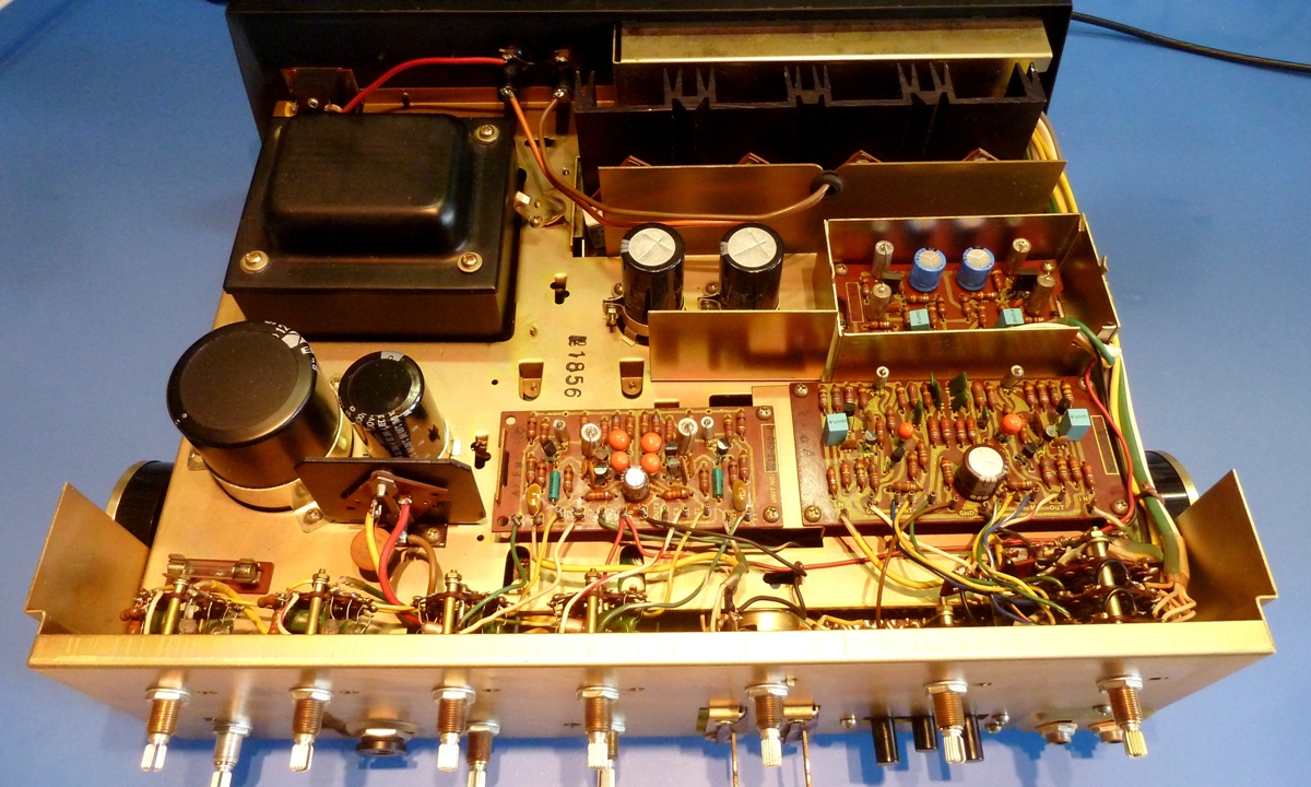
The amplifier top side, before the update
Top side, after the update
Ga naar Gerards page / go to Gerards other pages ---->>> ![]()
service manual Pioneer SA900 service manual Pioneer SA 900 service manual Pioneer SA-900 service manual schematic Pioneer SA900 schematic Pioneer SA 900 schematic Pioneer SA-900 schematics review Pioneer SA900 review Pioneer SA 900 review Pioneer SA-900 review reparatie Pioneer SA900 reparatie Pioneer SA 900 reparatie Pioneer SA-900 reparatie repair Pioneer SA900 repair Pioneer SA 900 repair Pioneer SA-900 repair