Ga naar Gerards page / go to Gerards other pages ---->>> ![]()

Revox a77 repair and electronic furbishment 2023
This A77 was sold to a well-known restorer called Piet, he replaced motor and roller bearings, and did further alignment using an official alignment tape. It is reported a top notch machine now, sounding extremely well.
It was a joy working on this machine. The reason for selling it was keeping it would involve buying big tapes and reels and needing to record, which would result in another extra hobby taking up excessive space and time.
![]() Gemakshalve is deze pagina alleen in het Engels geschreven.
Gemakshalve is deze pagina alleen in het Engels geschreven.
![]() This page is written using English language only.
This page is written using English language only.
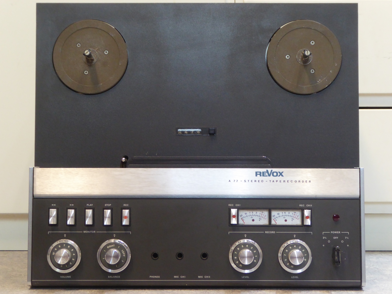
This iconic Revox A77 4-track 3.75/7.5 ipc mkIV was refurbished beginning of 2023.
I got it for cheap in a thrift store, reported defective and I could not resist buying it.
After realizing needing to invest too much into tapes, reels and needing to record a lot of music, I wanted to flip it, being intimidated by the piece, too.
However, I quickly found on the internet "everybody" is doing A77 restorations, so it can not be that difficult ;-) .
I decided to fix it, it was an interesting journey into this technology of the past, as I never tried to fix a taperecorder, before.
It was joyful working on it.
It is working nicely again, its biggest flaws were the seriously deteriorated trimming potentiometers to be found on the circuit cards and one of the power microswitches acting up.
I decided to just work my way through all electronic cards, as any problems would reveil itself, this way.
Therefore, I started with grabbing the little cards on the back, clean them, and put new components on them.
I used metal film resistors of 1% or even 0.1% tolerance having lots of those, instead of the carbon film resistors, on the cards passing audio signals.
As ALL electrolytic capacitors are measured they must be loosened, there is no reason NOT to replace them, so they are replaced by NEW or NOS parts, supposed to be of the same or better quality than the originals.
Still, most of them measured still good, and there was no single capacitor found which would keep the A77 from functioning.
Anyway, the electrolytic capacitors were all replaced.
If having film capacitors available and suitable to mount for their size, I replaced any electrolytic capacitor by using those.
The semiconductors were tested also, but I did not replace any of them, apart from the mentioned ones.
It was all those failed and deteriorated trimming potentiometers keeping the unit from working properly.
Enjoy the picture showcase, at the moment the subjects are in rather random order.

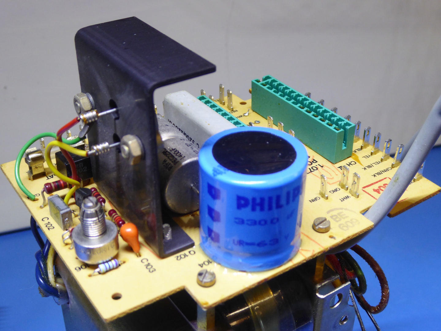
The DC power supply.
It did get a sturdy trimming potentiometer, electrolytic capacitors and a sturdyer small bridge rectifier.
There are two empty sockets, to cater for the (optional) 8 Watts output amplifier cards.
I did put in a Philips NOS capacitor to replace the old big one, I needed to drill holes to accomodate it. Basically it was here nor there, as it is not needed, as the (optional) power amplifiers are not installed.
The big yellow Frako 1000 microfarad one is replaced by a Rifa automotive one of 1400 uF. The old Frako type is reported to fail shorted, sometimes, on the Audio Karma audio forum). However, this is not backed by any evidence them to be less reliable than others.
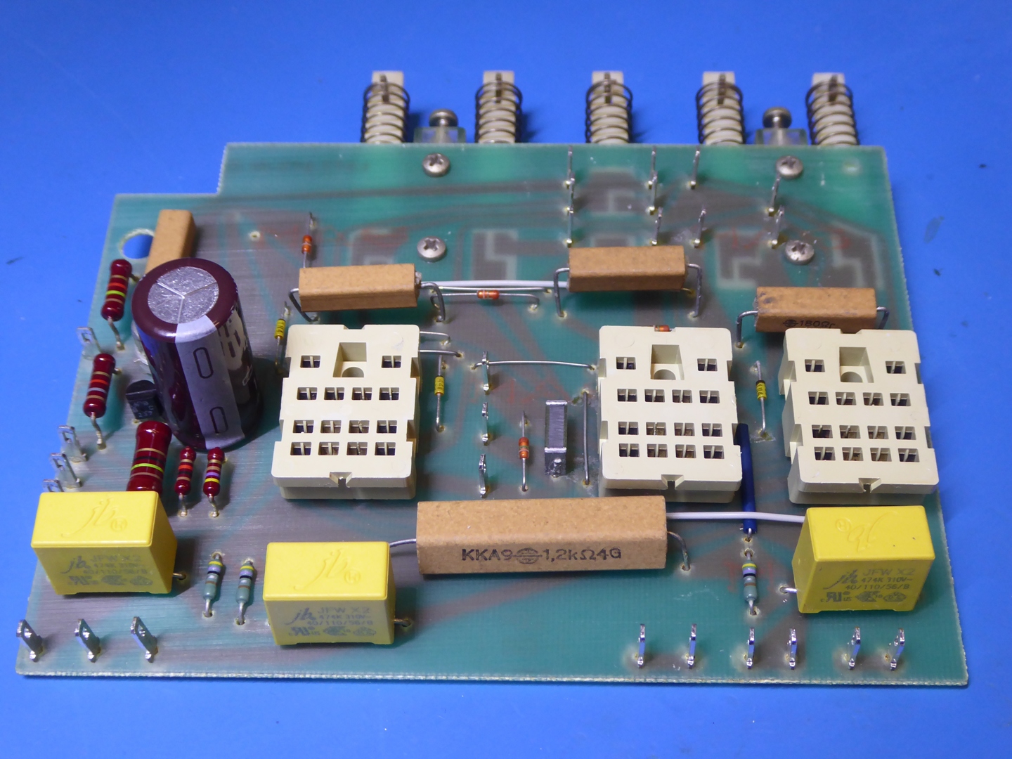
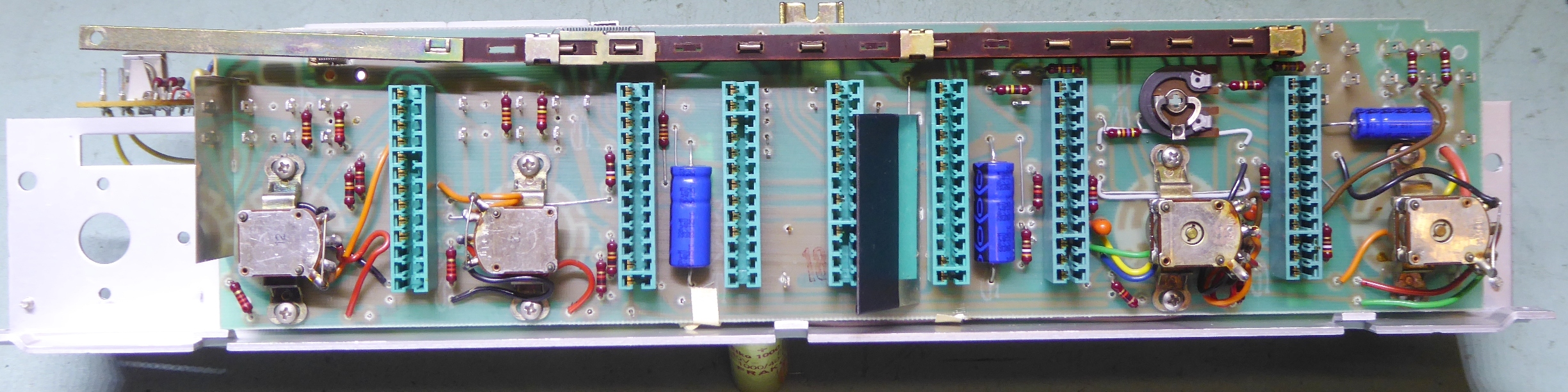
The Tape Drive Control card.
This card was disassembled and cleaned. As I had no replacement relays available, I measured the old ones by bench testing, they are still good.
The pushswitch contacts were tarnished, but measured still good. On the picture they are not cleaned yet, but I cleaned them anyway.
The plastic mounting looks vulnerable (the card carries the weight of the relays...).
It was a good exercise taking them off, as it makes me confident I do not need take the risk of disassemply potentiometers and rotary switches of the switch board if they would give no problems.
The still looking good but reported less-reliable Rifa capacitors were replaced. I had to buy new ones, but unfortunately the 21mm lead spacing is not to be found. The new ones are 18mm and can withstand a much higher voltage.
Holes were drilled to accomodate a radial big capacitor, having a suitable one.
The three little 4.7 Ohms COMPOSITE carbon resistors were measured, as they are known to drift over the years, and indeed one was over 10 Ohms already, one around 6 Ohms and one was still good. All three were replaced.
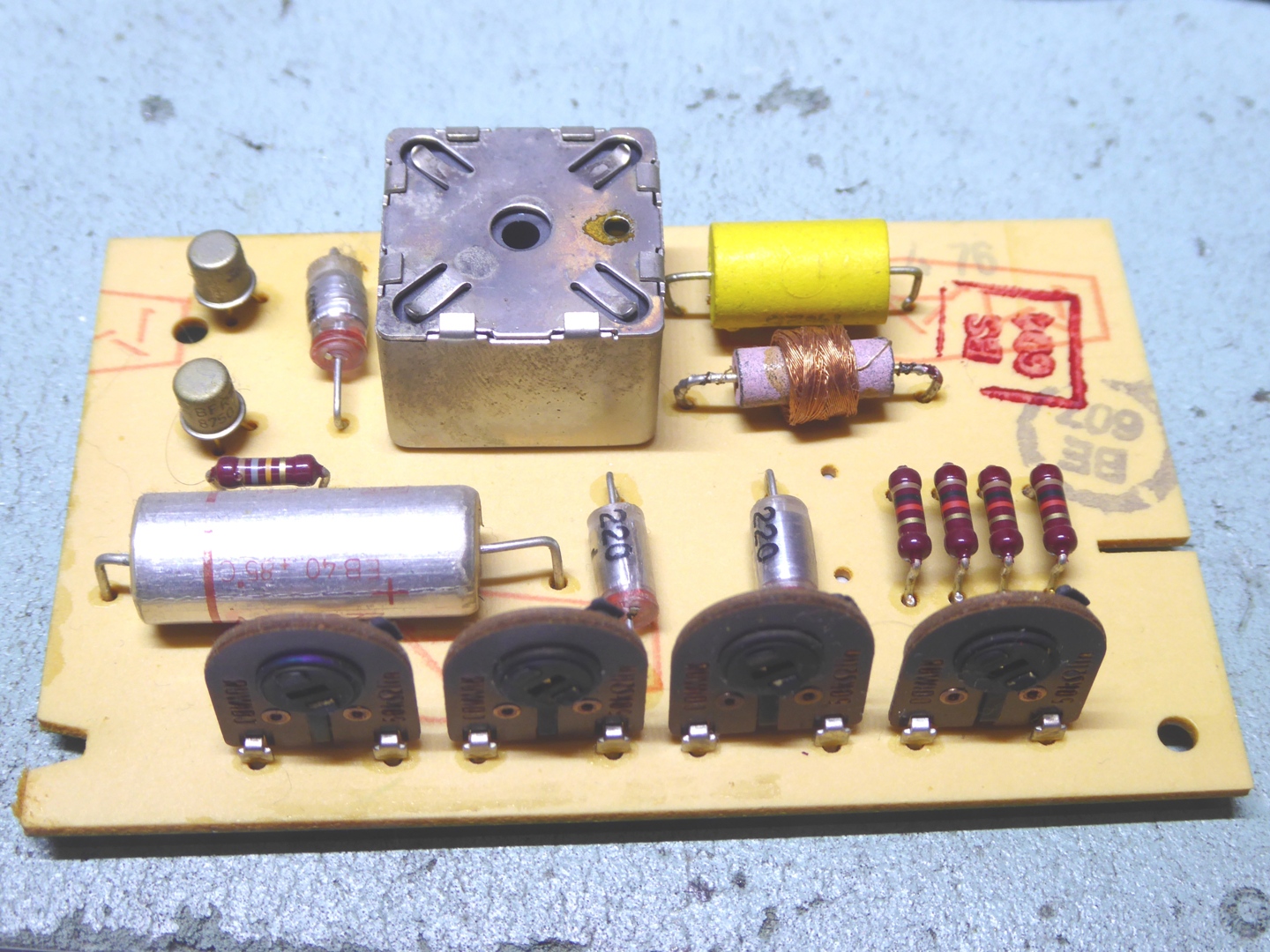
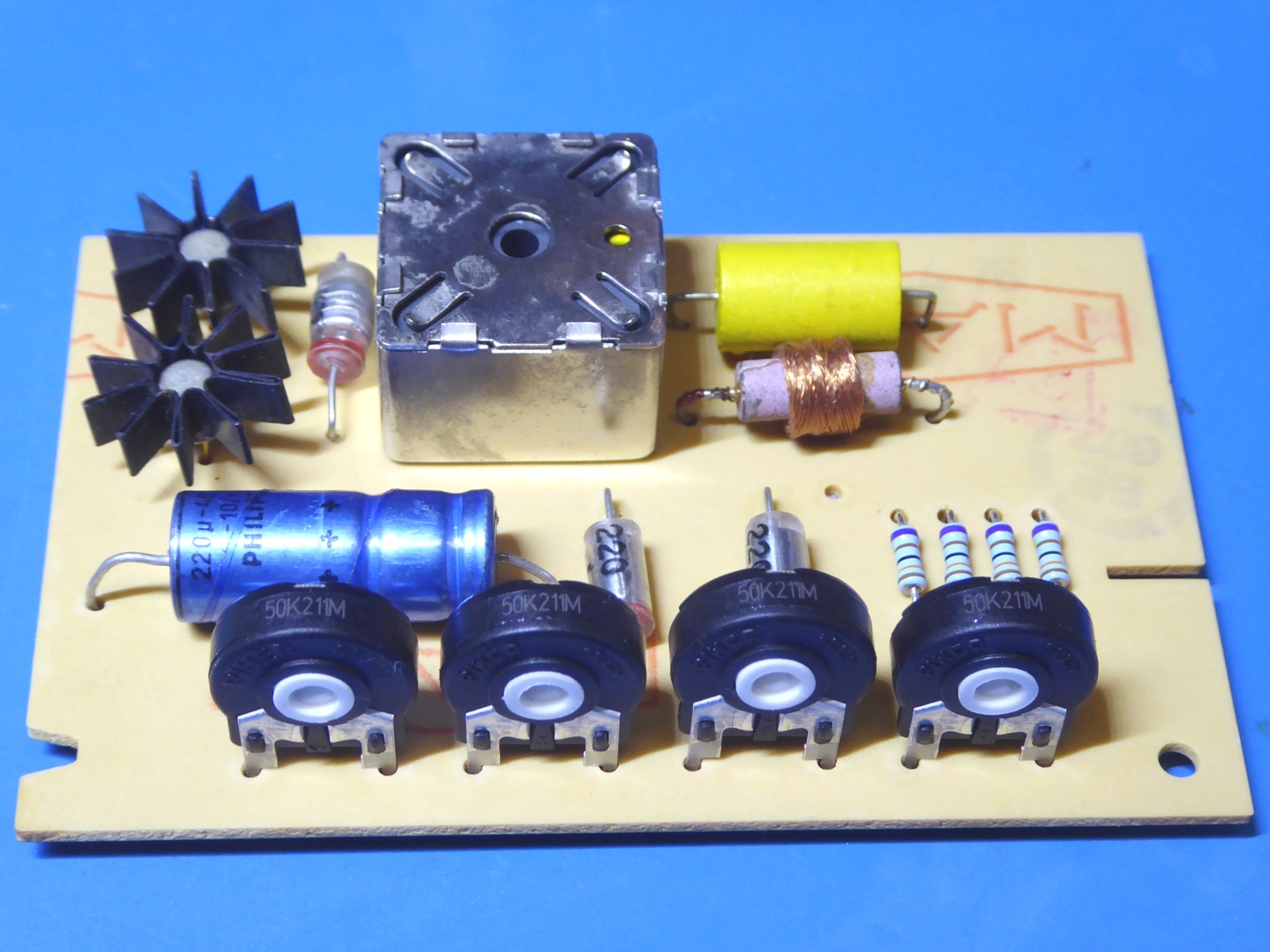
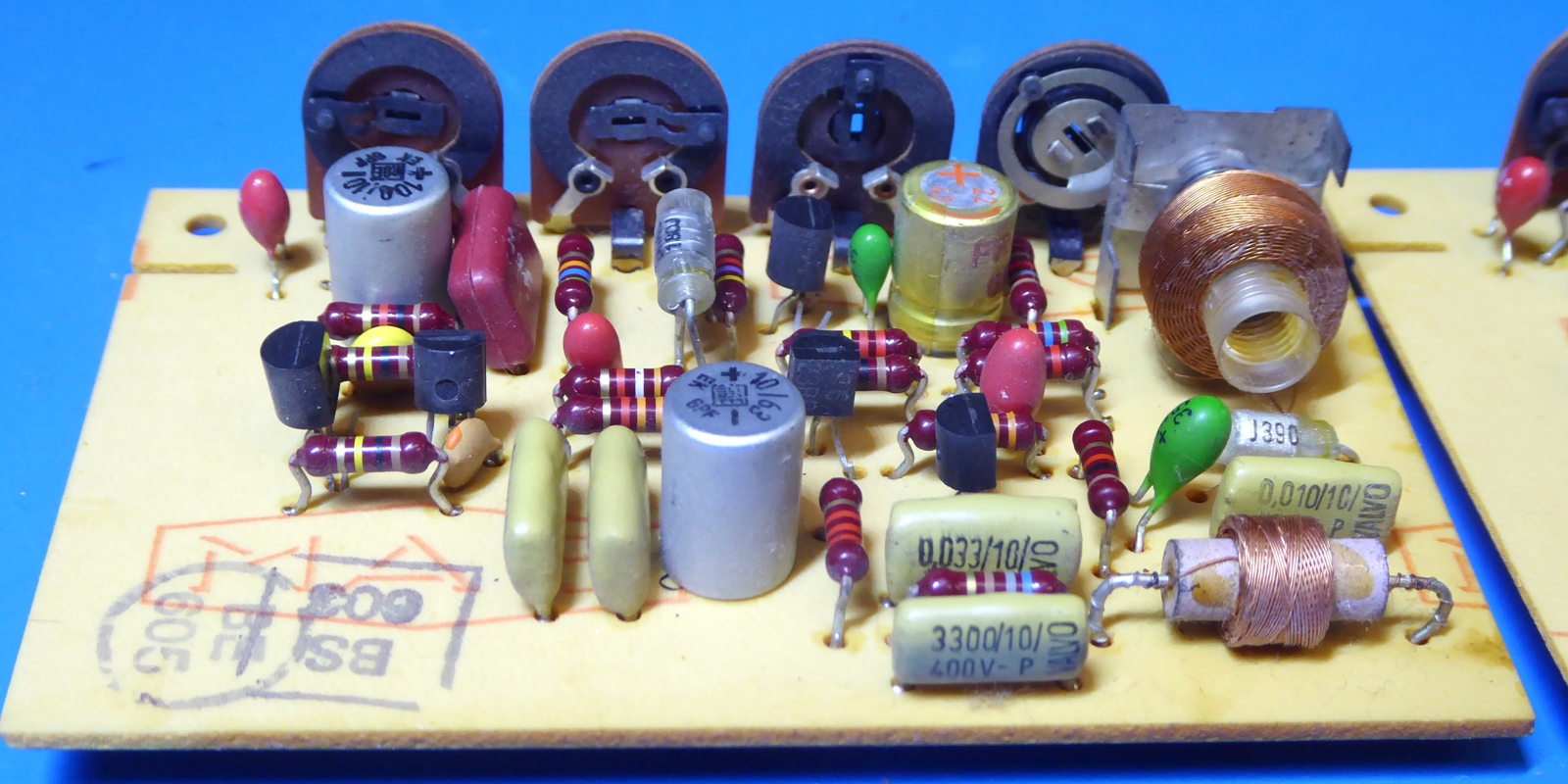
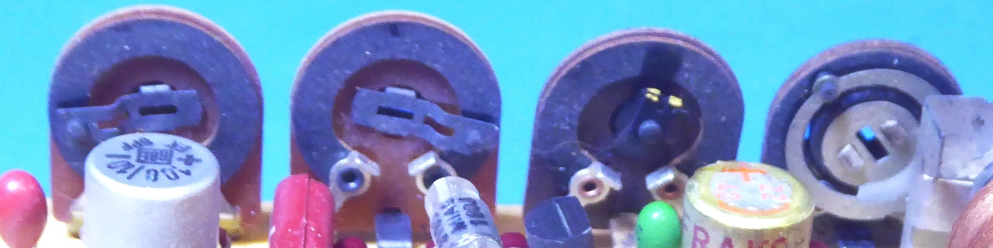
The Oscillator circuit card.
The oscillator board did get cleaning, a NOS measuring good Philips axial cap, new resistors, and the only real important thing, new trimmer potentiometers, as they were deteriorated.
The transistors are consired small compared the original ones specified for the A77 (BC140), so I decided to add heatsinks.
I decided to retain these original BFR18 transistors, there must be a reason they did put those industrial ones in, instead of the consumer-grade BC140 originally specified.
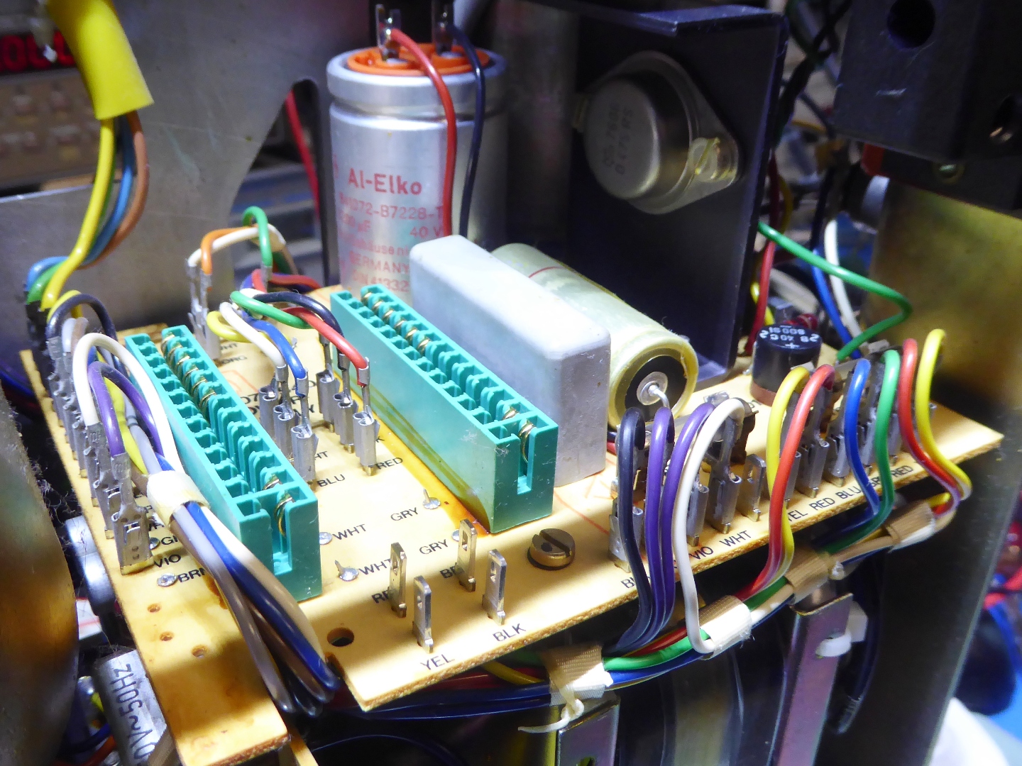
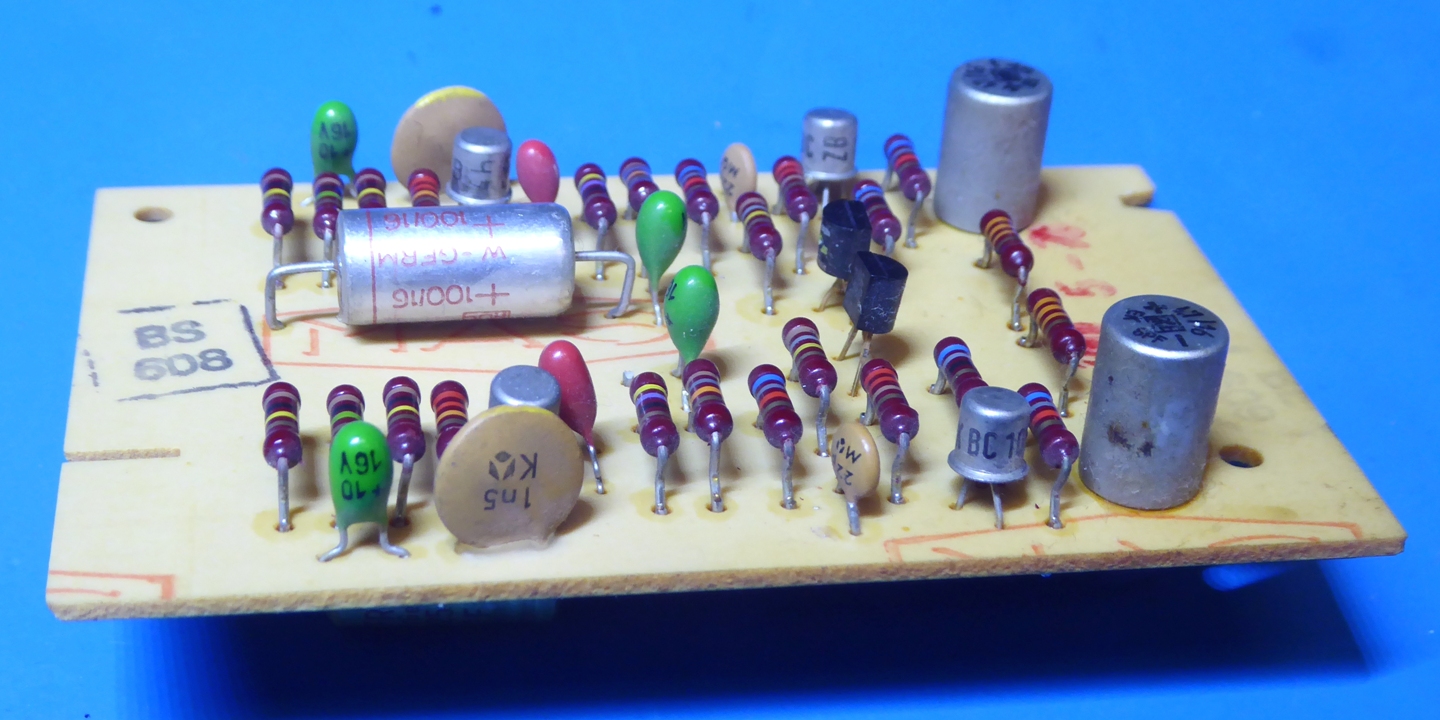
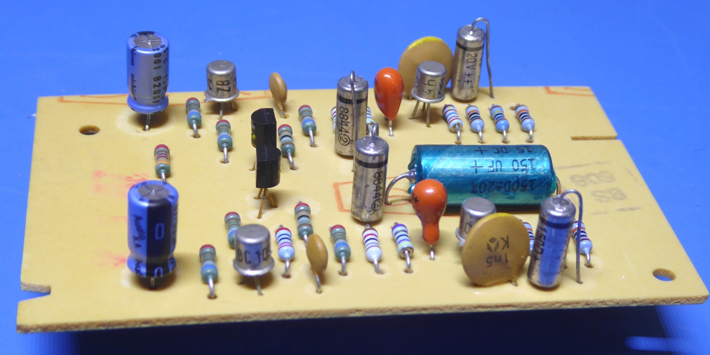
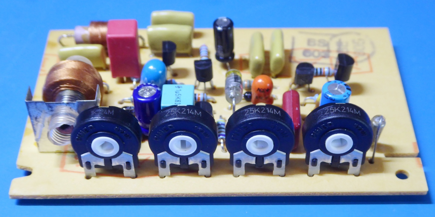
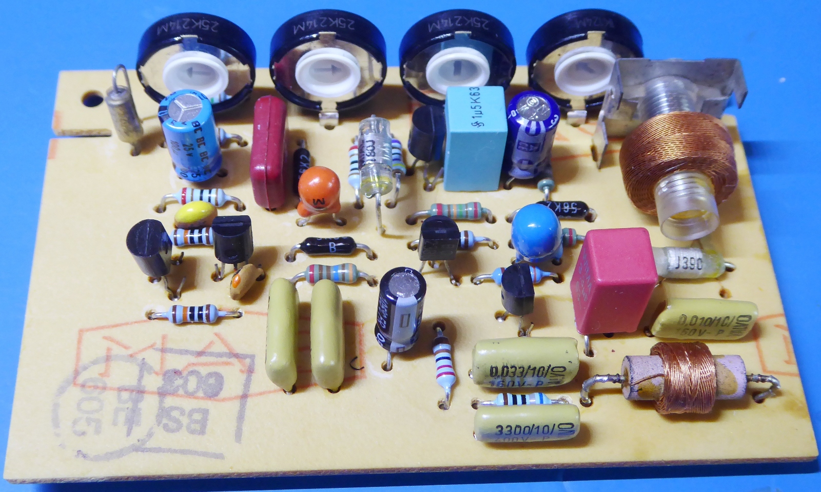
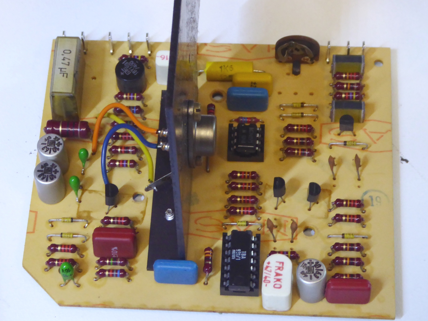
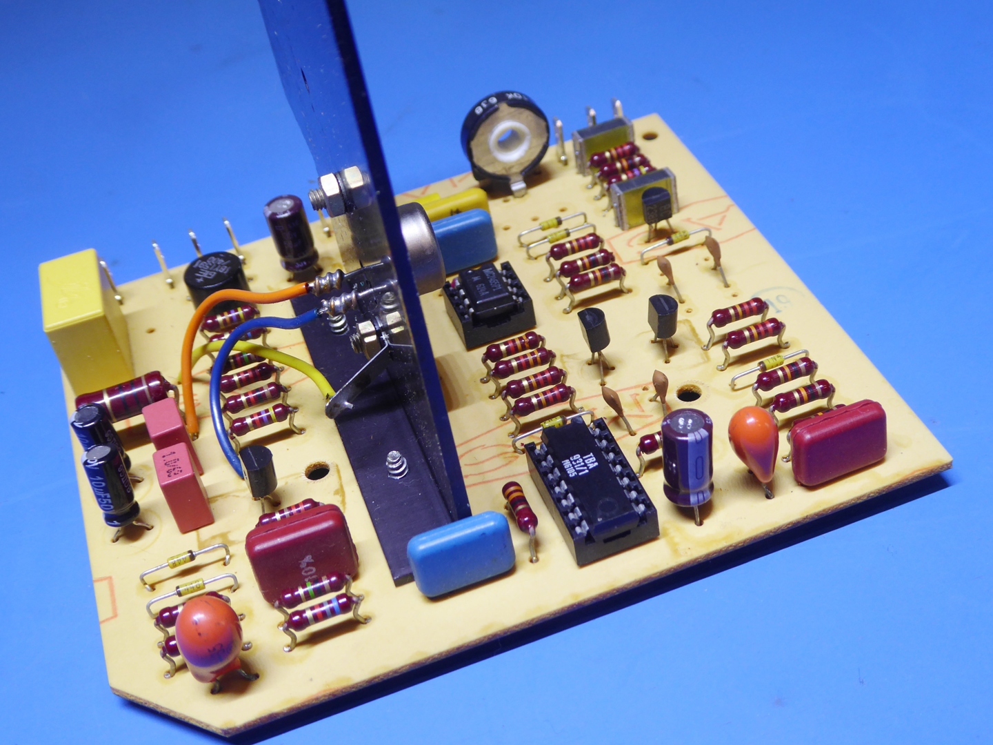
The Input amplifier circuit card.
I did put in other resistors and capacitors. All capacitors are measured on a Quadtech 1715 LCR meter before putting in.
The blue normal 47 �F electrolytics are Nichicon KA, the rest are all Tantalum capacitors, all resistors are low noise metal film now, 1% and some even 0.1% tolerance.
Not thinking twice when there was a big box of 0.1% tolerance resistors available on the Dutch "Marktplaats", you see such only once, so now it is mine....
Observe, one of the big capacitors is mounted on the bottom, as all A77 have it mounted that way. I can think of no other reason than to minimize crosstalk between channels.
I checked against other pictures on the internet, it seems normal.
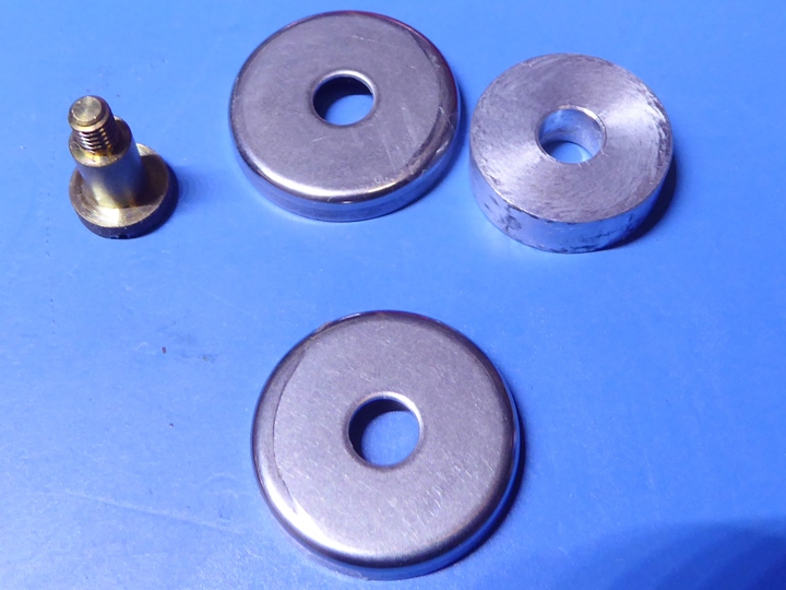
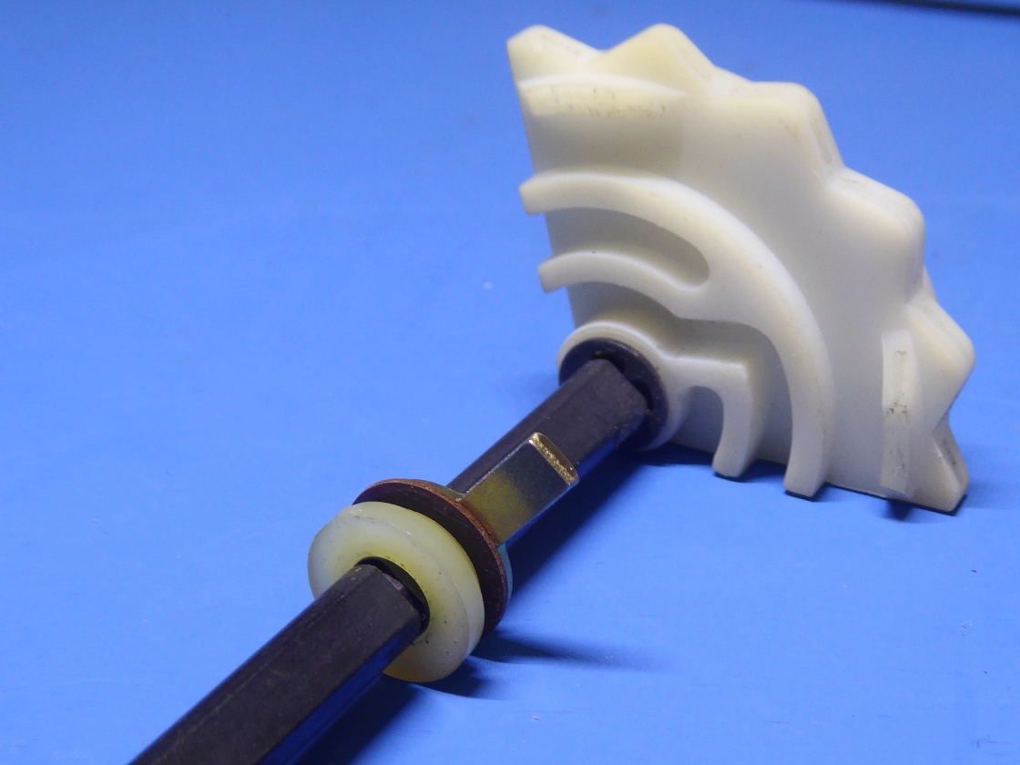
Some mechanical stuff.
Cleaning was needed, here, as can be seen on the picture below.
I took the roller out and cleaned the shaft, as it was not rolling smoothly. It was also cleaned on the outside as there was brown residu. I know, alcohols on rubber is "not done" but when you dry it instantly it can not do harm. One does not want to have rollers deteriorate because of the wrong cleaning agents...
I was very surprised to see the tape guide on the RH side to be a fixed one having an aluminium piece.
At first I thought, somebody replaced a roller guide.
On the internet I read, people replace it using a roller, indeed, but originally it is really a fixed guide, and there are some internet discussion whether replace it by a roller or not.
Therefore, it is not a problem, and I have no reason to doubt the Revox mechanical engineers.....
Still, I polished the aluminium a little, and to make sure, I put it the other way around, so the "never-used part of the guide" is in use, now.

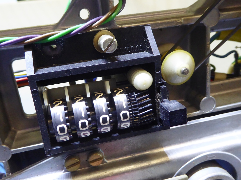
The Tape counter.
The sprocket-belt as well as the rubber belt were defective. Probably the sprocket-belt is unobtainable or expensive, I replaced it using a rubber belt. It looks working fine. to be sure, I put a second one on it. It stays on the wheels.
I do not know if it lasts, but on the internet there are rubber belts suggested as replacement, also.
Still, a little mechanical problem remains, as the plastic nulling pushbutton seems stuck most of the time. Maybe I have to examine the mechanism.

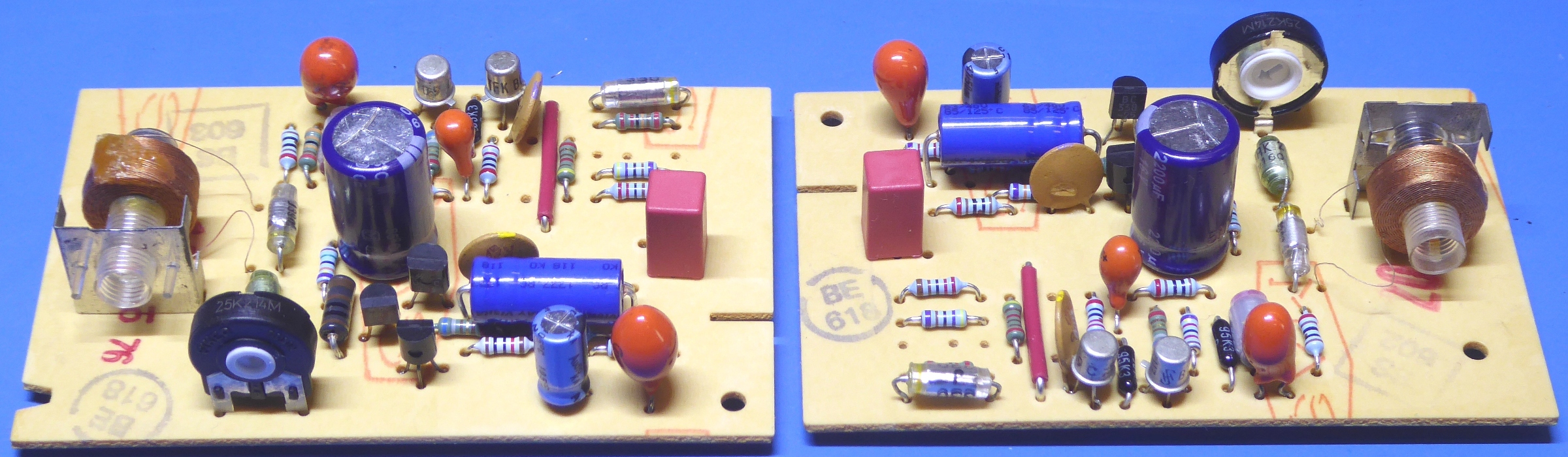
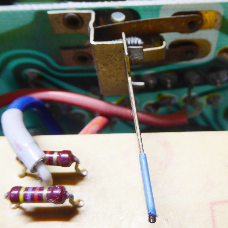
The Playback and Drive amplifiers circuit cards.
I forgot to make pictures of the cards before putting on new components. As on the other audio cards, all resistors are metal film ones, now, some capacitors are replaced.
During dismantling, it was found one of the coil wires was loose. It could have happened over the years, who knows how many years it was not used...
The Switchboard.
The switchboard was checked, throughout, using a DMM the resistance of contacts was measured.
Fortunately, all seems working well, so there was no need to take apart the switches, nor the potentiometers which are probably "unobtaniums".
To have good access, some desoldering and resoldering has to be done on the connection between the meters carrier board and this one.
The odd-looking S5 playback cutoff "switch" was checked and it had its pcb contacts cleaned.

The few electrolytic capacitors were changed out, and the trimmer potentiometer, tweaked to end of its range already, was replaced by a NOS one.
The Record amplifier.
This amp also suffered from seriously deteriorated trimming potentiometers.
One wiper broke apart, trying to turn it....
Throughout this A77, I took care of keeping the very same alignment of the new potentiometers, compared to taper resistances and taper orientation.
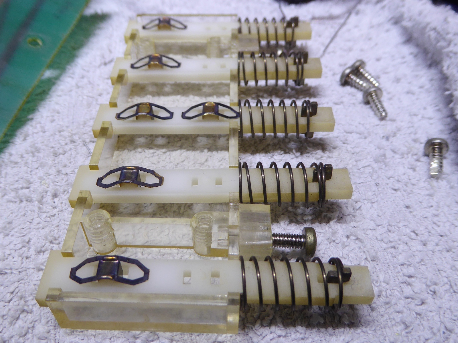
The Power / Speed selector switch.
The power switch consists of a rotary selector, actuating a set of three microswitches. One of the switches was defective because of being broken apart, I was lucky to find the very small broken piece still in the recorder....
I did not have the very same size microswitches available.
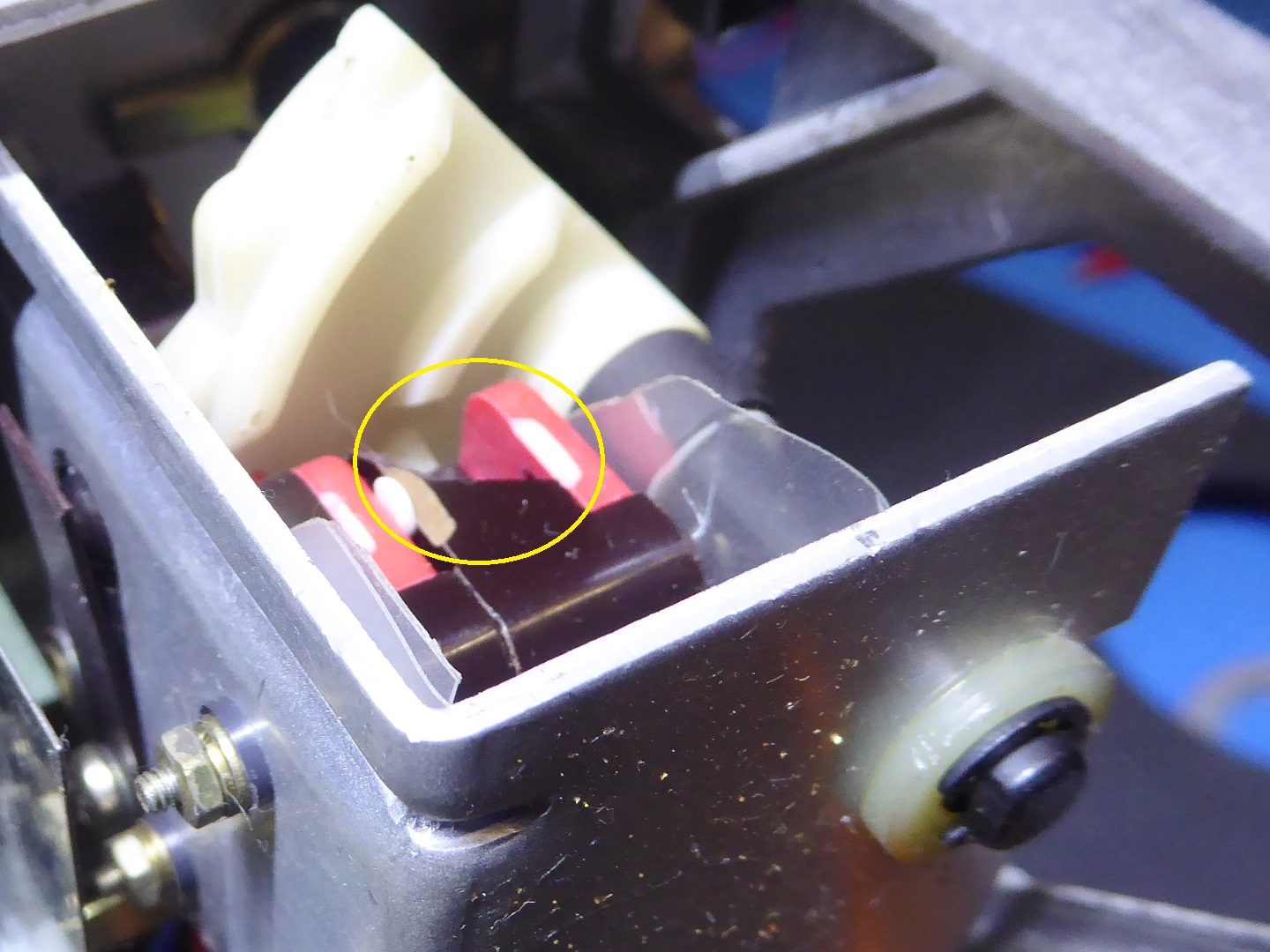
The switches were unbolted from the bracket. I applied some high-strength glue on the little piece I found, and fixed it back onto the microswitch.
I drilled a strong pcb drill into the little glued piece, all the way into the bakelite housing and then I broke the brittle drill at the edge.
The metal pin remains in the plastic and bakelite, so it is stronger than it ever was.
I remounted everything, and I did put some extra of this glue called "repair extreme", also on the other microswitches, as a precaution.
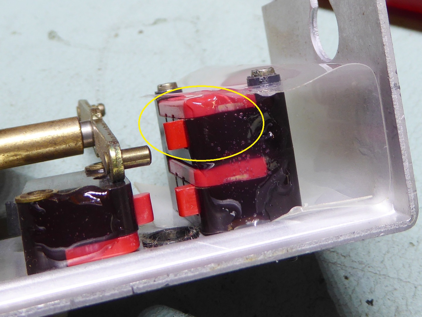
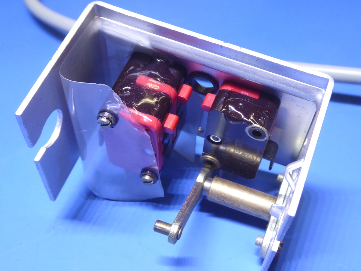
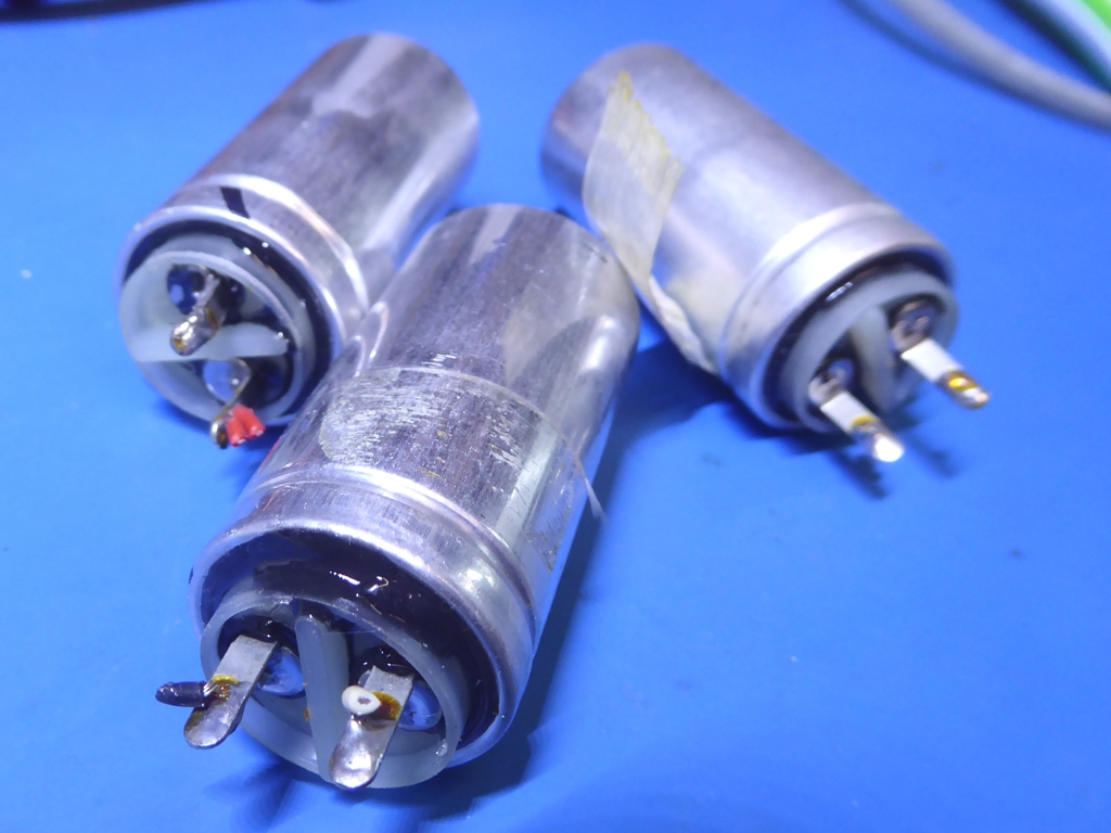
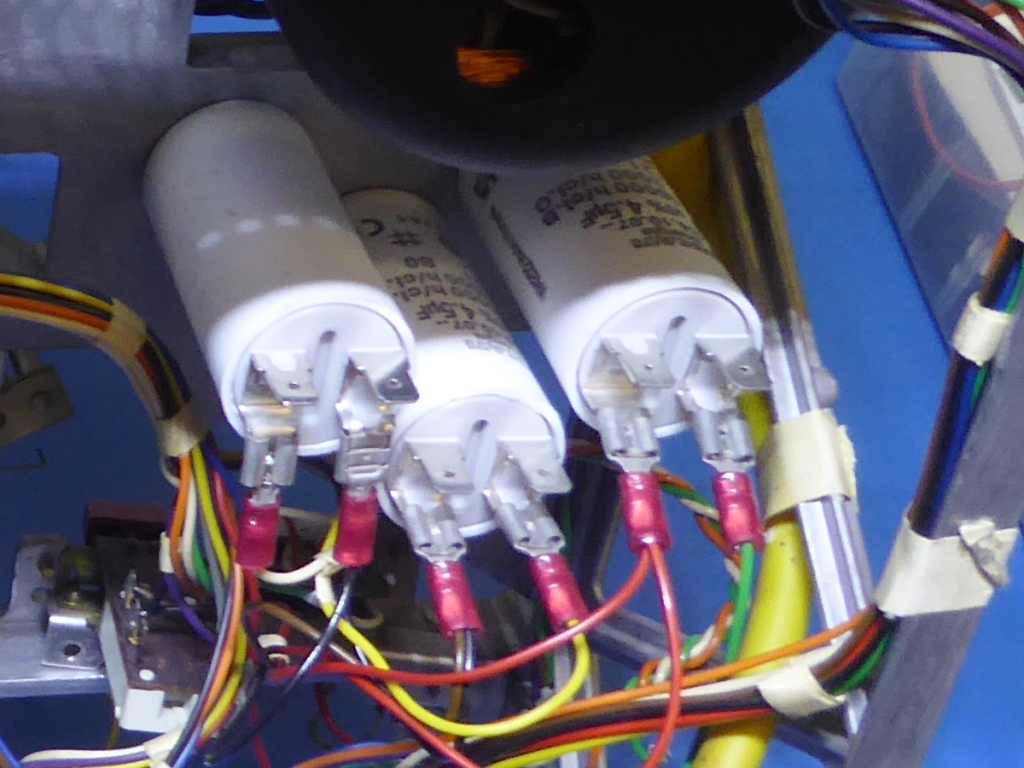
The Motor Capacitors.
The motor capacitors measured still good, but they suffered from tacky deteriorating rubber sealant, easily identifyable on the picture.
I have no idea, whether it has any impact on reliability, but if it would start dripping, it could result in a mess on the long term.
I bought new ones, I used the "faston type" terminators instead of soldering the wires, as the caps were designed for that.
It looks more in line with the A77 design, as it is full of the (smaller type) of these connections.
Physically, the new capacitors are smaller than the old ones
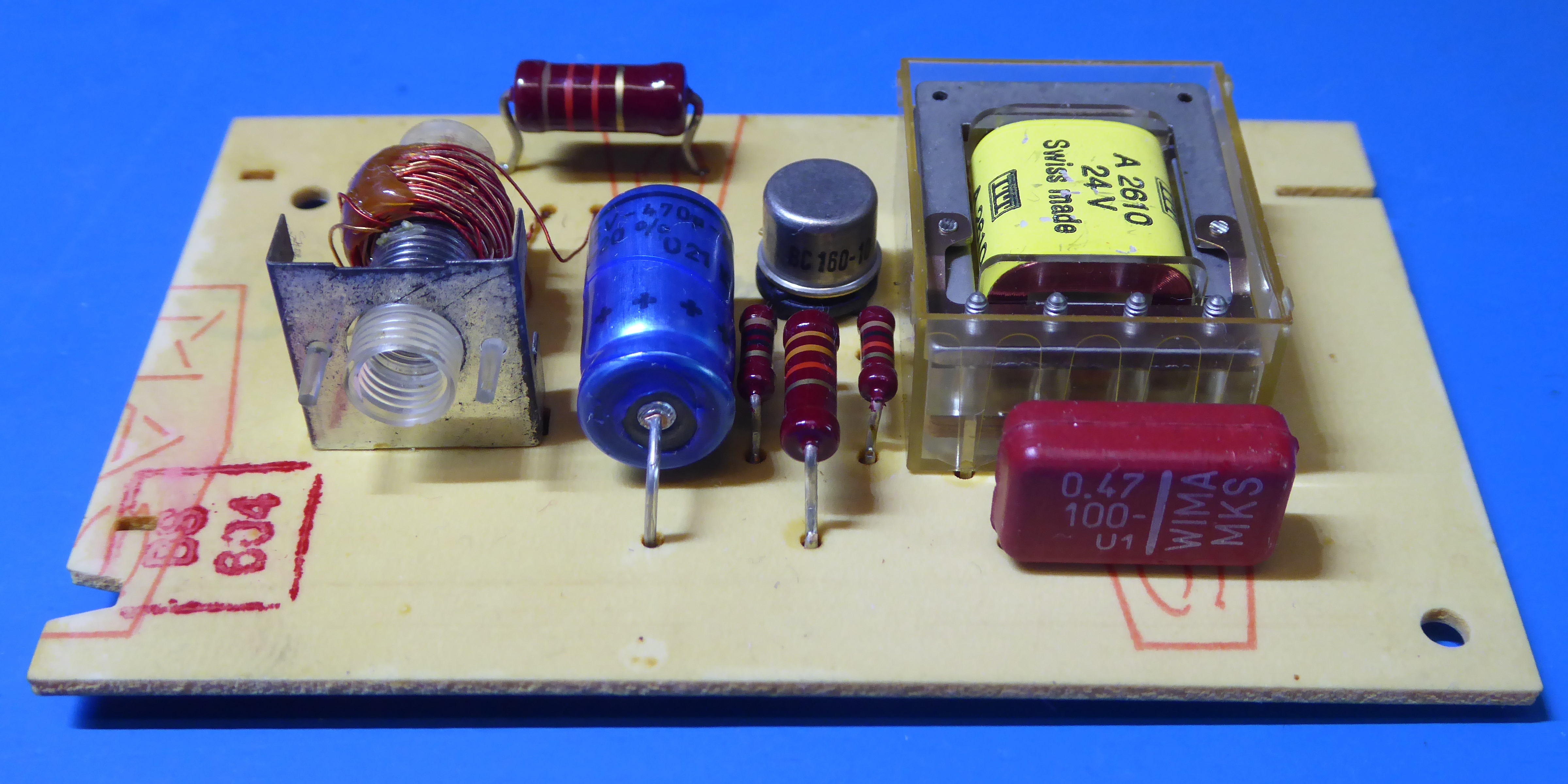
The Speed Control.
The trimming potentiometer, electrolytic capacitors were replaced, including the also on this card present 0.47uF Rifa capacitor.
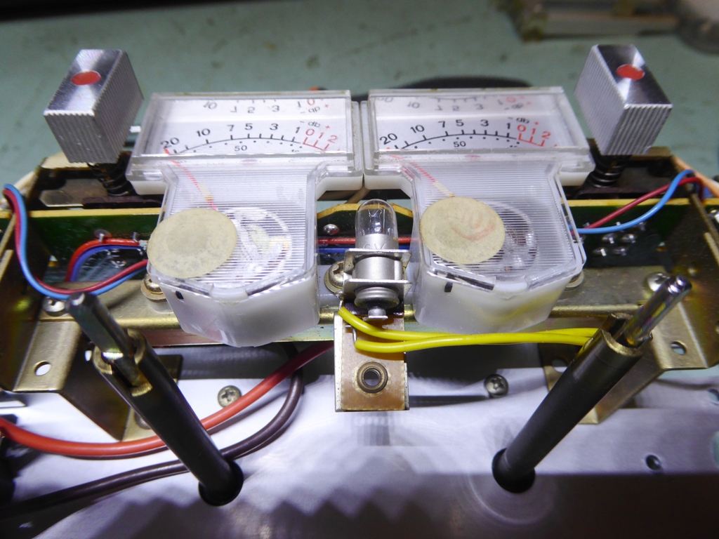
The Record relay card and the VU meters.
I decided to use a BC160 instead of the old Germanium AC152 transistor, for reliability.
The meters are said needing glue to fix the magnet of the mechanism to the plastic, so I put some in. I still have to evaluate if I put it on the right spots, reading some other comments, later.
BTW: Care must be taken, as no glue must touch to moving coil....
The bottom of the recorder, close to finishing this project
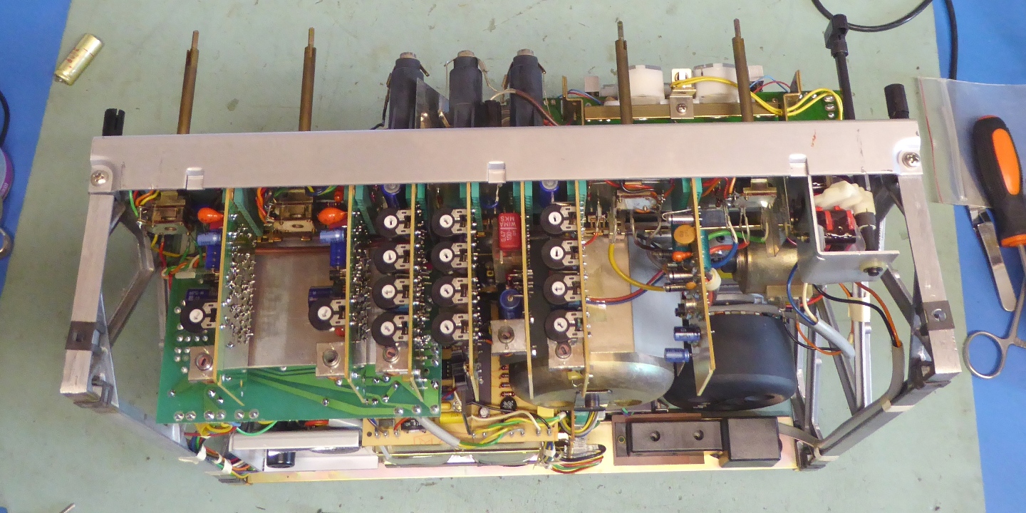
The back of the recorder, close to finishing this project

The A77 front
Ga naar Gerards page / go to Gerards other pages ---->>> ![]()