

Sansui 661 refurbishment October, 2024 


Gemakshalve is deze pagina verder in het Engels geschreven.
![]() This page is written using English language only.
This page is written using English language only.

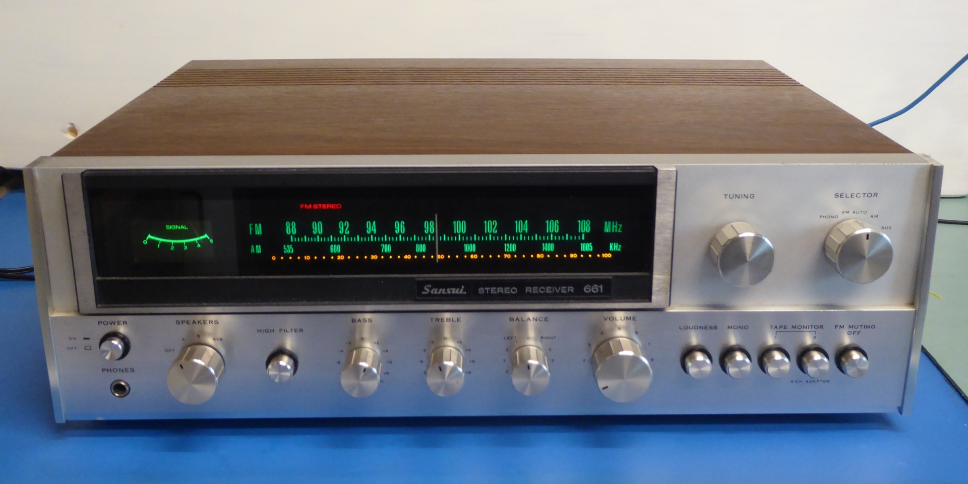
This good looking Sansui 661 was bought reported "it worked perfectly until one day smoke came out".
There were no visible problems, but it smelled right away after power up. The heat source I found using a Fluke 62 handheld reader. After finding the reason on the power board I decided to give it a recap/refurb, and fix defective lighting, assuming the tuner and amplifier circuits worked.
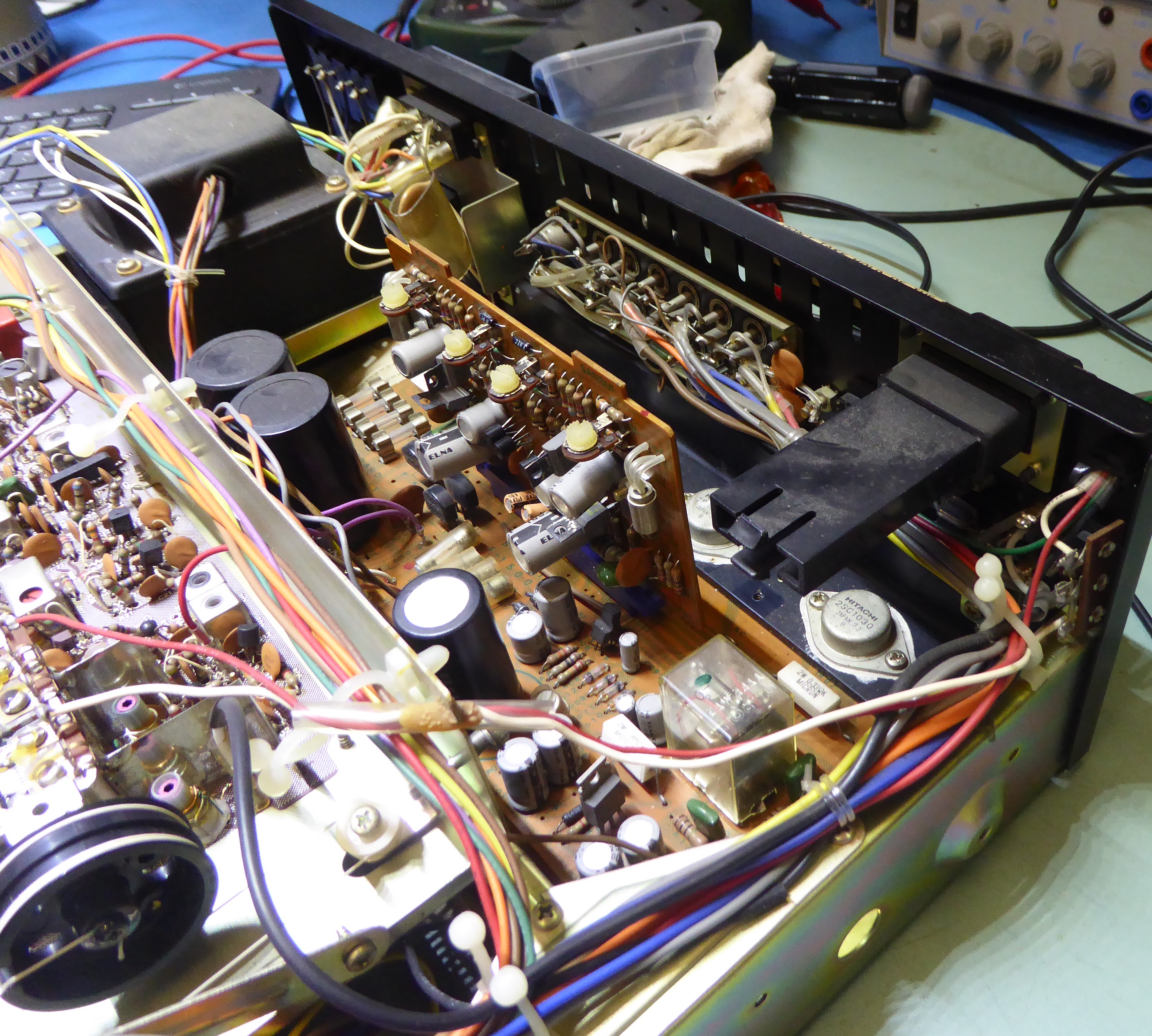
The innards of the receiver looked clean, for its age, and unmolested. It is a well-built receiver, and it was a joy working on it.
All information contained on this page assumes interested readers to provide themselves with the schematics and manuals as to be found on the internet.


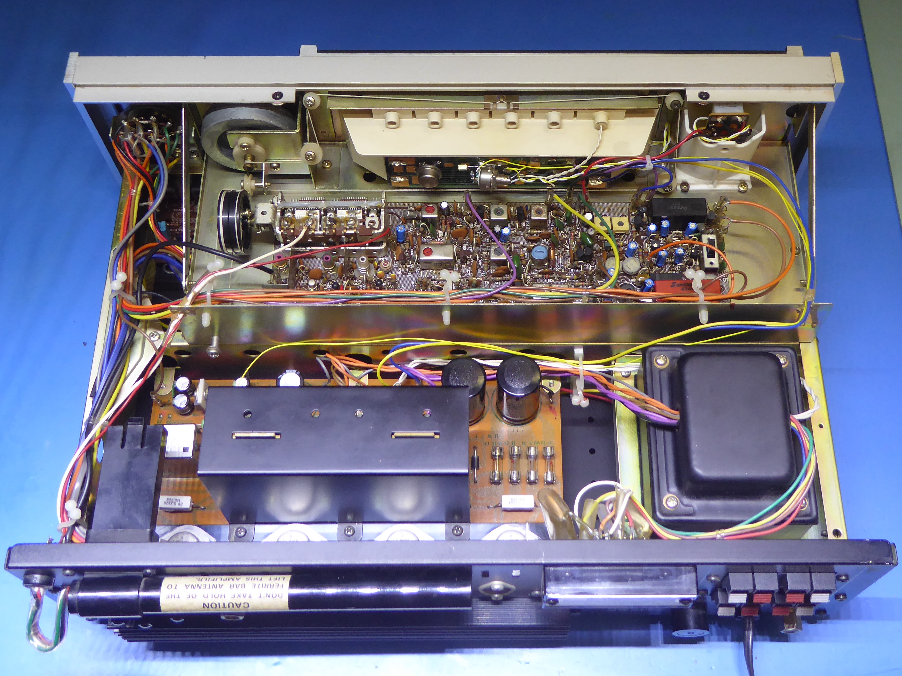
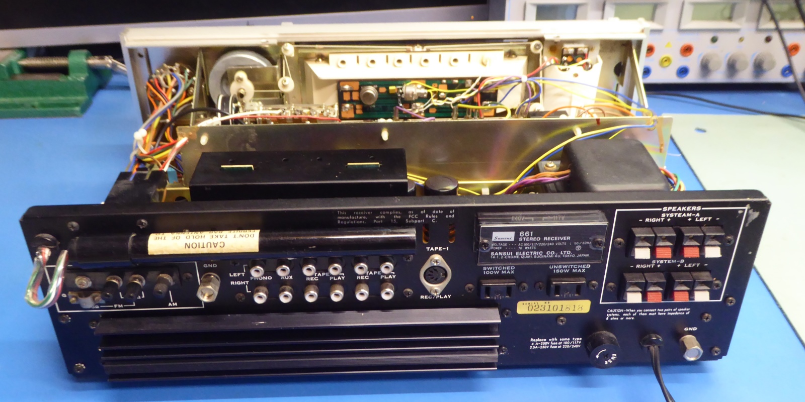
The innards of the not-yet-refurbished receiver from the top.

Note: the cover of the main amplifier circuit card is removed.



The sansui 661 F-1500A Power Circuit Board
This board contains the transformer connections and power distribution, rectifiers, and stabilization circuits.
Additionally, it carries the main amplifiers circuit card F-1499A on a circuit card, and the associated power transistors including their mounting/heatsink, as well the relay operated loudspeaker protection circuit

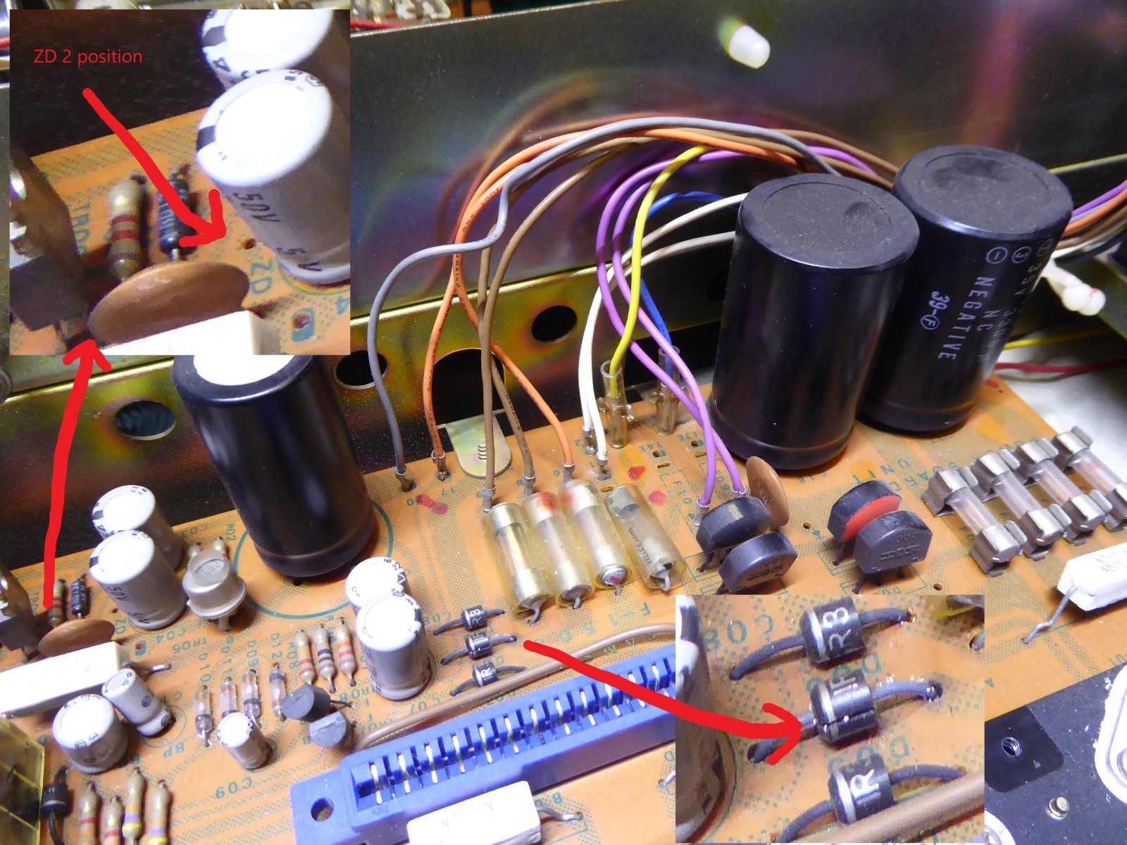
On the picture below, there were two capacitors looking extremely hot according my infrared thermometer device. On the enlarged part on the bottom, a defective cracked diode seemed to be the cause.
The enlarged part on the left reveals a hot spot on a ceramic cap and the impression was this could also be because of a hot TO220 type 2SD330 regulator transistor.
The ZD2 zener diode was missing, it was found on the bottom of the card, since the holes drilled did NOT match the schematic.
One of the soldered-in fuses was defective, also.




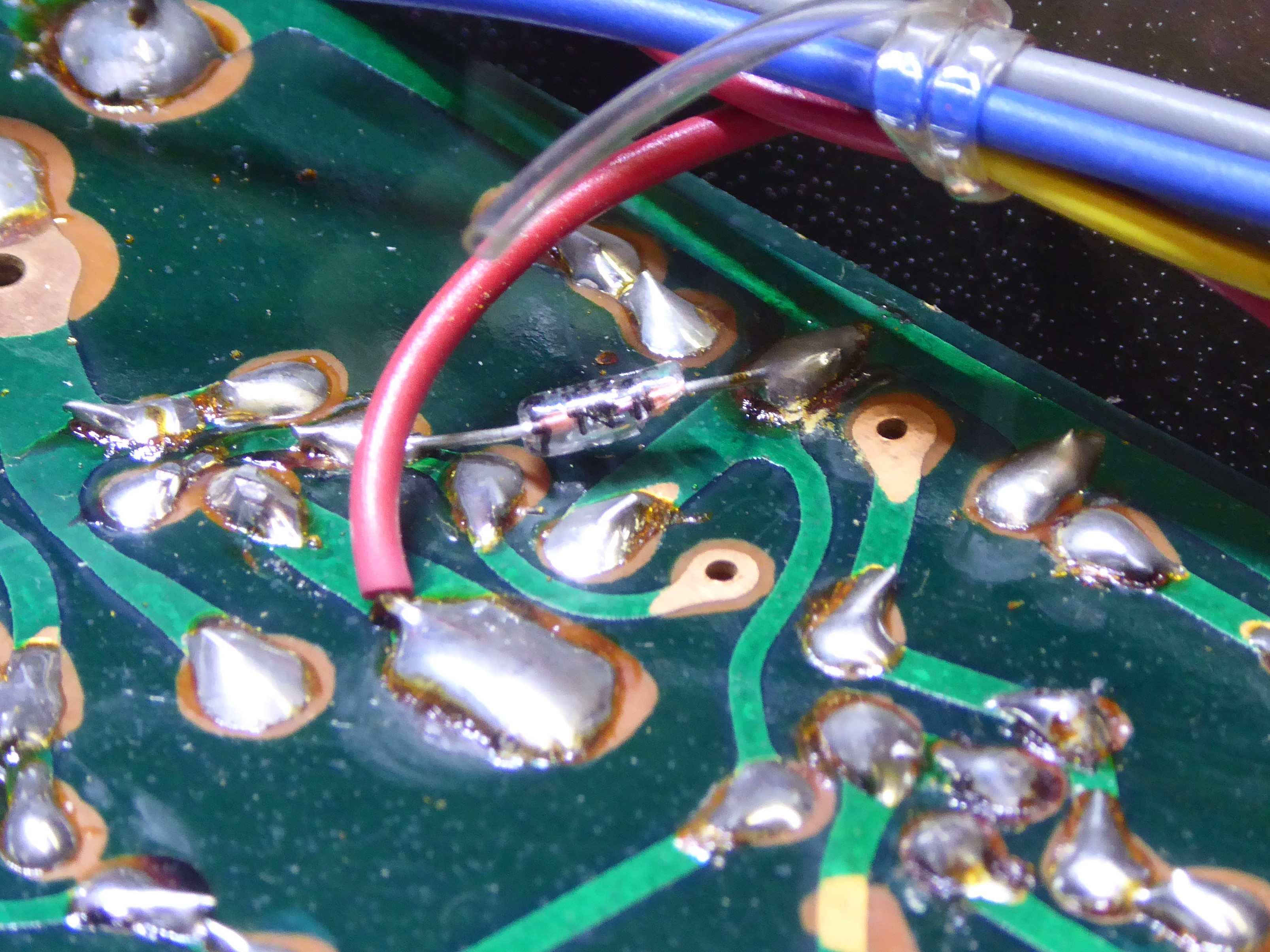
The ZD2 diode was found on the bottom of the card. Af funny detail is when the board was still powered on and the zener measured, one more piece of glass cracked off but it still worked.
I decided to depopulate the card, after having repaired and tested it first.


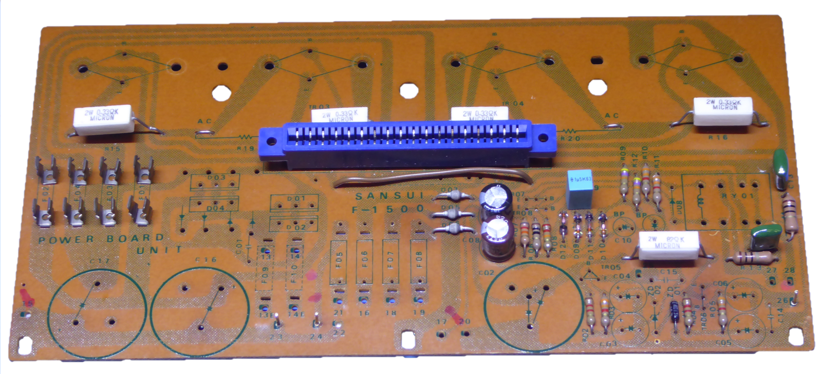

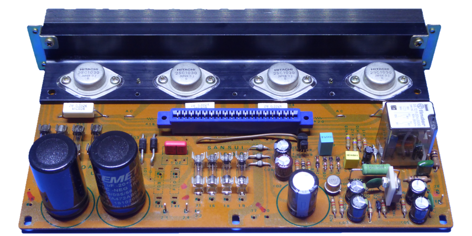
I replaced the three diodes, as well as the one supposed to snub the relay switch-off effects, by "fast soft-recovery BYV96E" rectifiers, they are more rugged than the originals.
The old rectifier diode "double pairs" were replaced by 1N5408 diodes, also more rugged compared to the originals.
The 3300 Microfarad power smoothing capacitors by Kemet ALP22 4700 Microfarad ones, and the 1000 uF one for the regulated supply by a 2000 uF Panasonic FR type.
Although they were still fine, not replacing those would have been "half a recap"....
Also other electrolytics were upped for capacitance if assumed appropriate. The soldered in fuses are socketed ones now, a hole on the right position was drilled to have ZD2 on the component side of the circuit board.
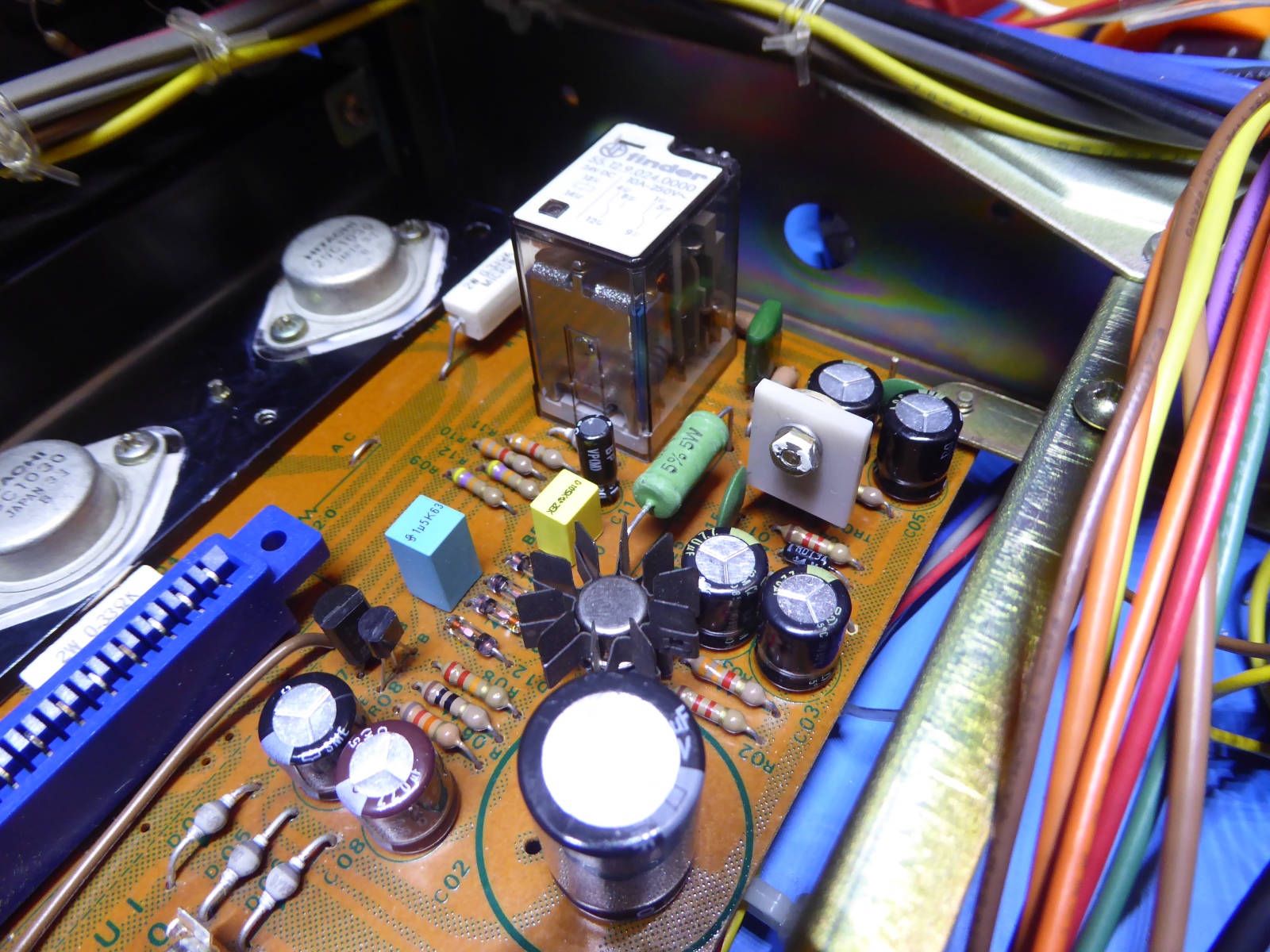
Although the old relay worked, as part of the update I decided to mount a new one, so it can work for many years again.
I decided on a more robust driver transistor for the relay, a KSC2632, driven by a 2SC945, now.
Both power regulating transistors did get a heatsink, the 2SC875 later on replaced by a more rugged 2N3440 including a cooling fin, to accomodate a lighting modification demanding a then unestablished yet current increase.
This all makes the Power Circuit Board look much different, although it functions the very same, apart from being more rugged and electrically better than it ever was!
The amplifier power transistors did get new thermal paste.

The extra "heat sink" on the 2SD330 actually simply consists of a TO220 heat conducting ceramic mounting plate, it is not conductive electrically. Additionally the power resistor over there was raised up for better heat flow. In the end, it looks everything stays pretty cool, now. The cooling fin on the 2N3440 proves "overkill".
There was a pcb hole to accomodate a pin at the 23 Volts regulator output, it was not used since it was just wired at the bottom. A nice place to put in A pin to feed the lighting modification.



The power amplifiers card, F-1499A "Driver Circuit Board"
I decided to recap the main amplifiers card but not a total rebuild. The thermal compensation TO-1 style VBE multiplier transistors are thermally connected to the driver transistors, changing all out I found it too much of a hassle, it would imply making some metal mounting bracket.

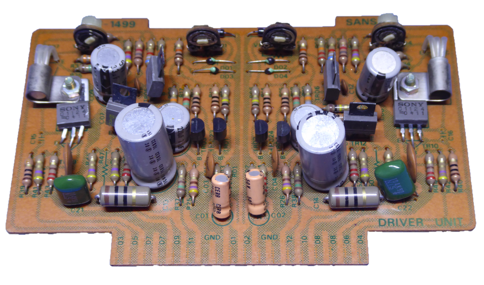

An electrolytics recap was done. As usual, I replaced the small values electrolytic types by film types, having better specs and nil leakage.
The input transistor pairs were replaced by closely matched pairs of Onsemi KSA992.
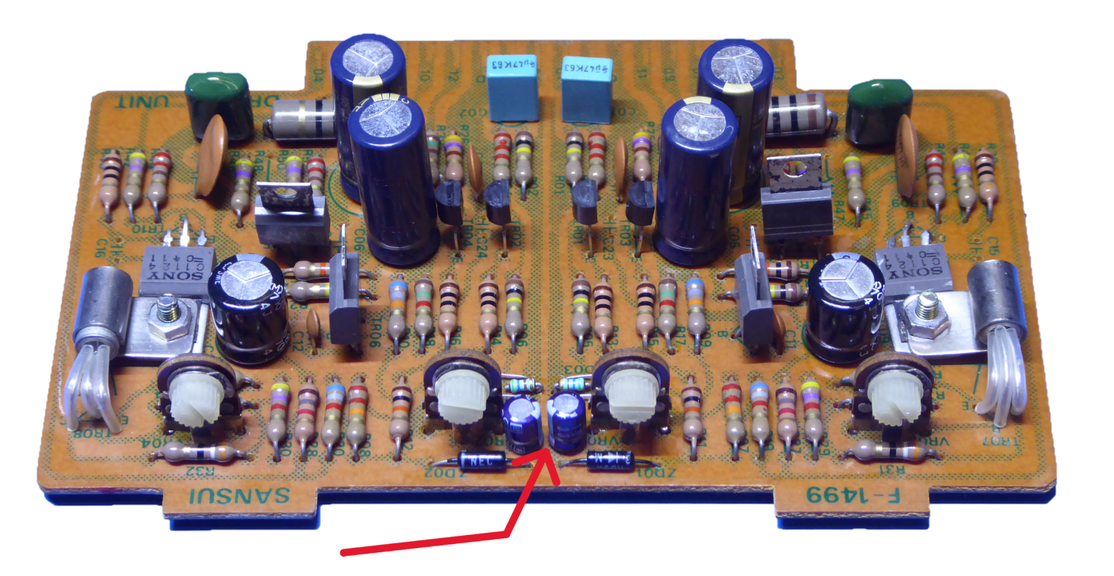
Due to the offset trimming design, its trimmer potentiometer was much too sensitive, due to the diodes as a reference one can swing the offset to 0.6 Volts!
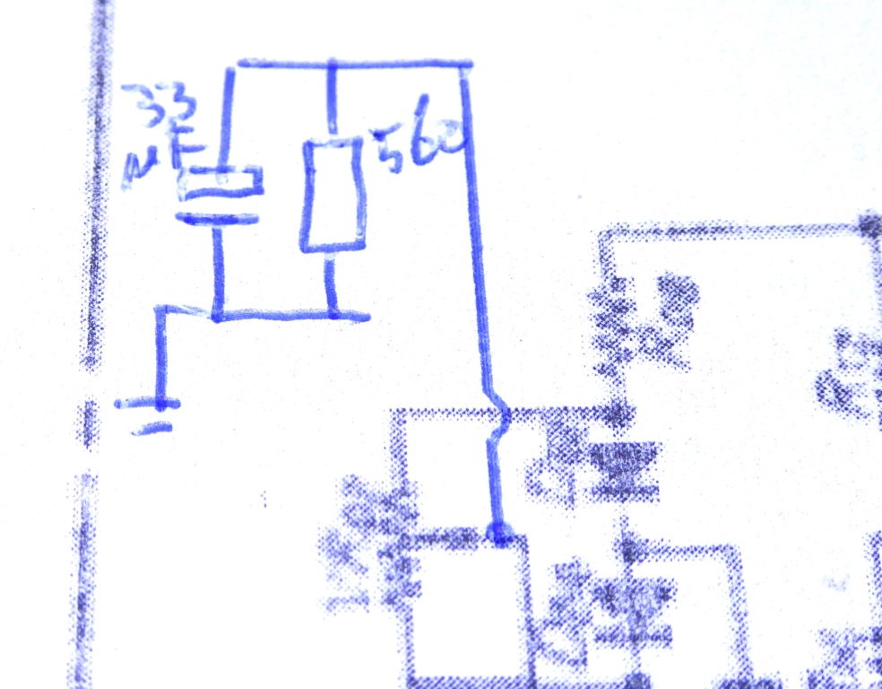
I drilled holes and put the trimming potentiometer taper to ground using small 560 Ohms resistors. Also two small 33 uF capacitors were added to stabilize any fluctuation because of power supply changes or noise of the trimming pots. (see the arrow on the picture) Now, trimming the amplifiers DC offset voltages to millivolts is a piece of cake.




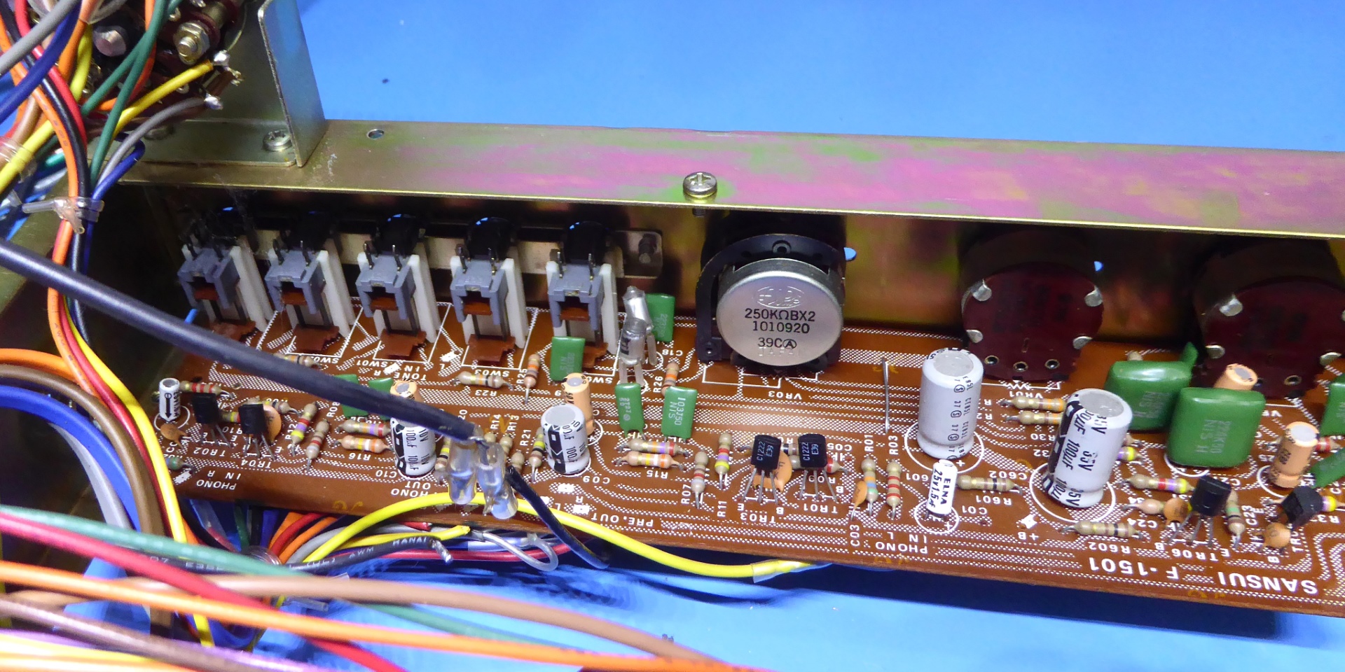
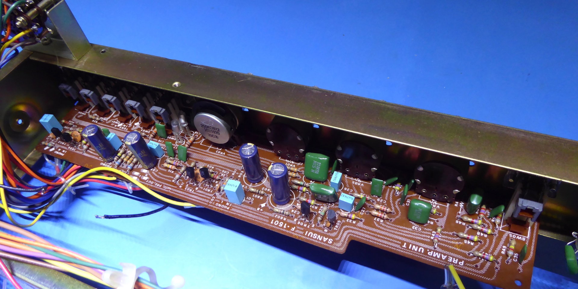
F-1501 Preamp Circuit Board.

This board was recapped, using assumed suitable components, using film capacitors to replace the small-value electrolytic capacitors.
The bigger ones are nice 220uF 63V Panasonic FC, it is "overkill" but as I have a lot of them, why not use them.
A nice service-friendly feature of the receiver is the fact one easily can remove the tuner section, therefore working on the preamp card was easy, without needing to remove it.
Observe, there are no signs of spray being used on potentiometers, this board is still quite clean.


The F-1491A Tuner Circuit Board.


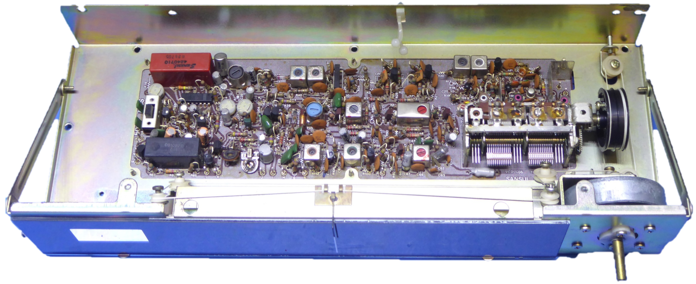

Two tarnished trimming potentiometers were replaced by square looking yellow ones, for peace of mind.
All the electrolytic capacitors were replaced, most of them are blue 4.7 microfarad BC ones, now.
This was the only work done on the tuner section. Because of the whole tuner module could be removed, this easy.
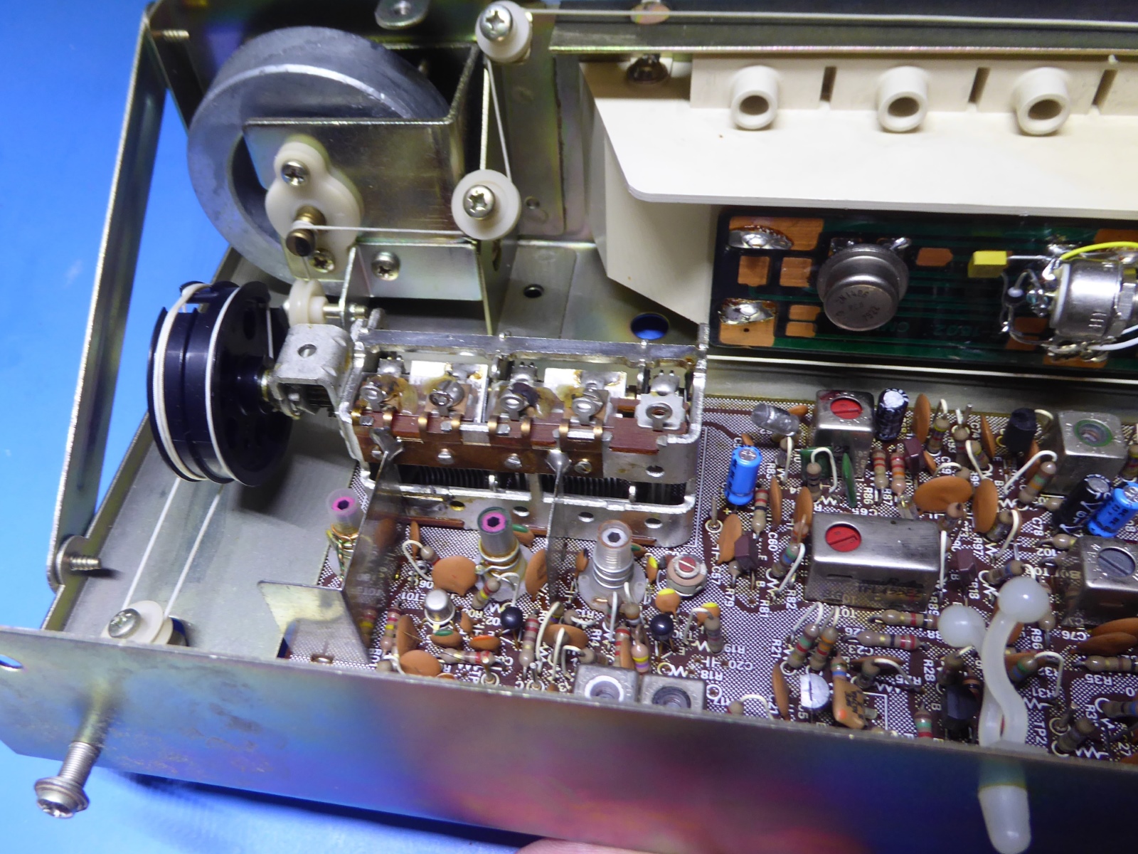

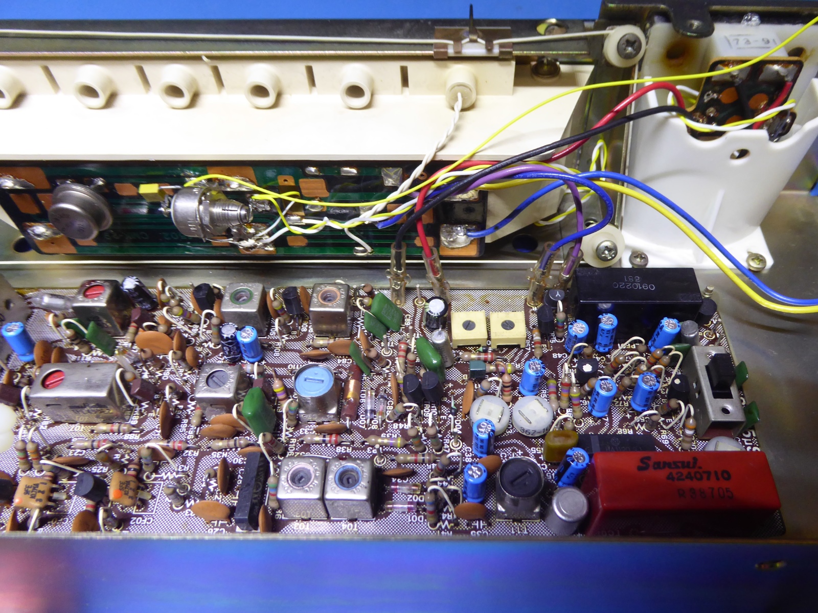


The receiver lighting.

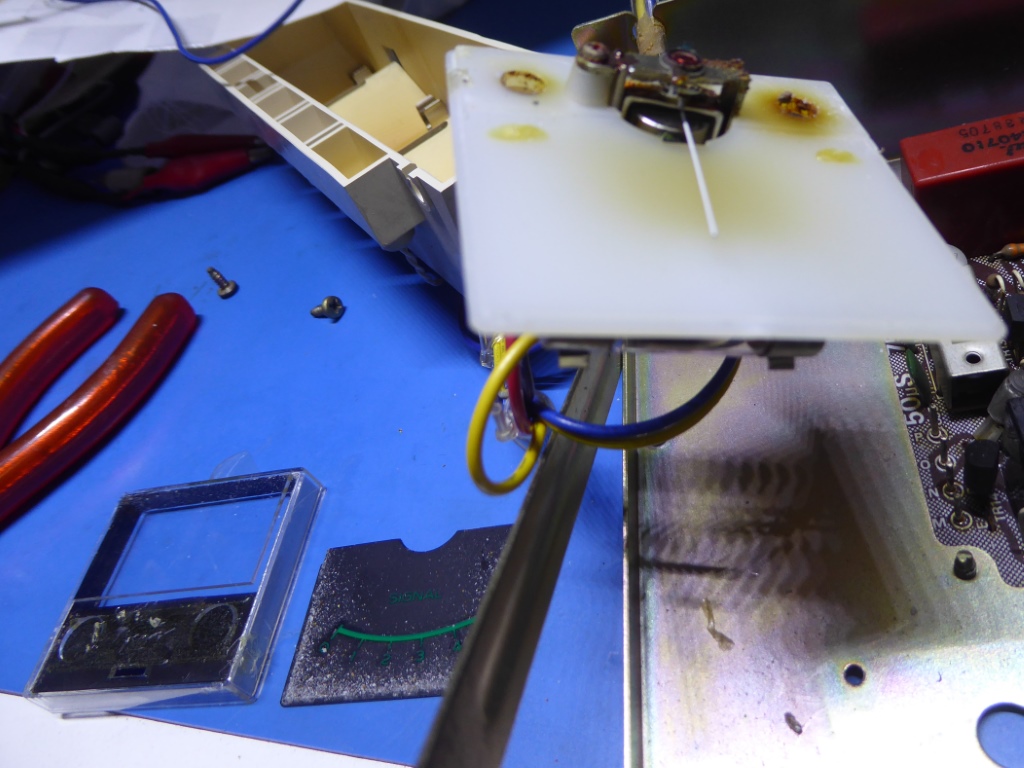
The old lighting was partly defective. The meter backlighting consisted of one backlight tubular lamp and two tiny 5 Volts lamps in holes in the plastic back of the meter.
Below, the picture of the disassembled meter shows some debris caused by one of the little lamps witch apparently burned. I had to take the meter apart and clean it.
The scale backlighting comprised of three 7 Volts tubular lamps, also those were replaced by a LED string.
I simply do not want those ready-to-use but otherwise inferior for light dispersion fuse-style LED replacements one can buy.
Next to it, is the picture of the type of LED string, including size, spec and partnumber.
Unfortunately, I forgot to make pictures of the work on the lighting. On the tuner section above, one can see the additional parts mounted on the back of the lighting module. I mounted a quality potentiometer, to adjust the brightness as desired!
The stereo lamp remained as is, so this is not a LED.



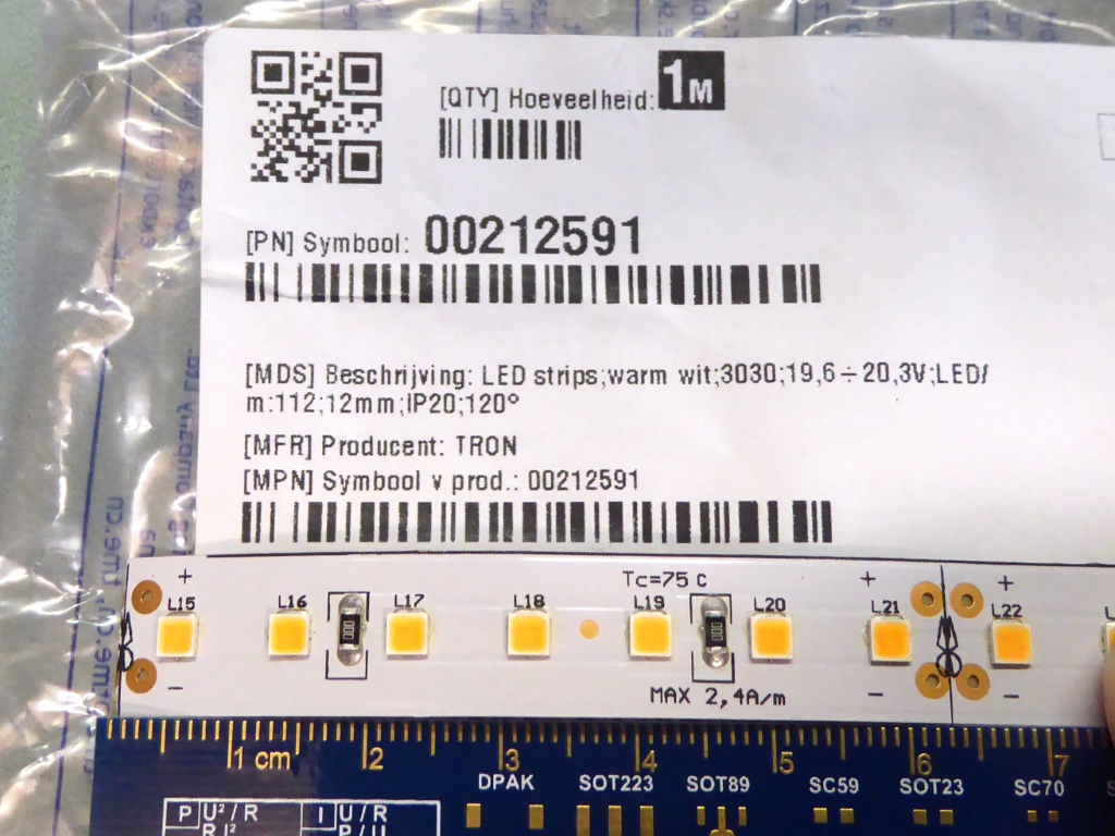


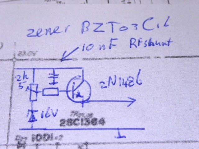
I used a nice big round 2N1486 transistor (see the ridiculous prices for these at Mouser etc), a 16 Volts BZT03C16 Zener diode, a 2.5K trimming potentiometer to feed the LED strings for the meter and scale backlighting. (see them mounted on the tuner section pictures).
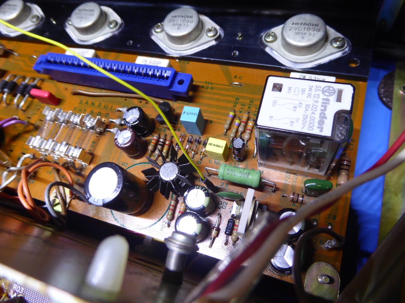
On the picture on the right one can see the previously unused hole on the circuit card, where the 23 Volts is taken, using a additional wire going along with the wiring to the lighting module.



![]()

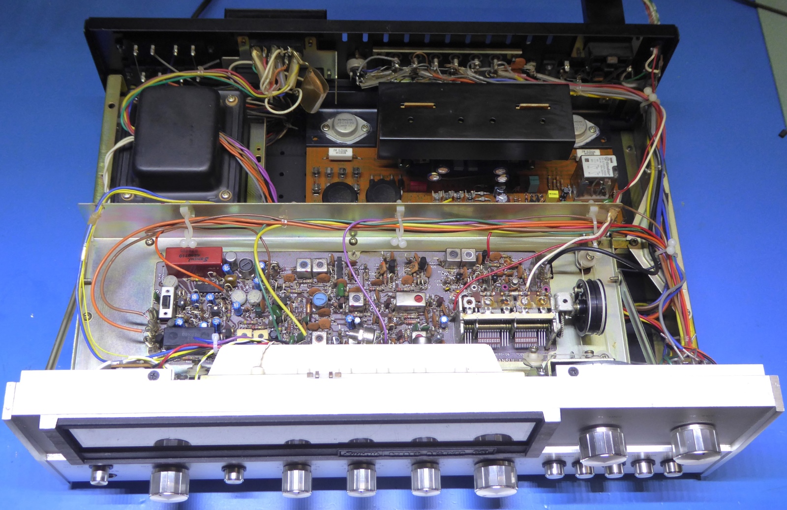
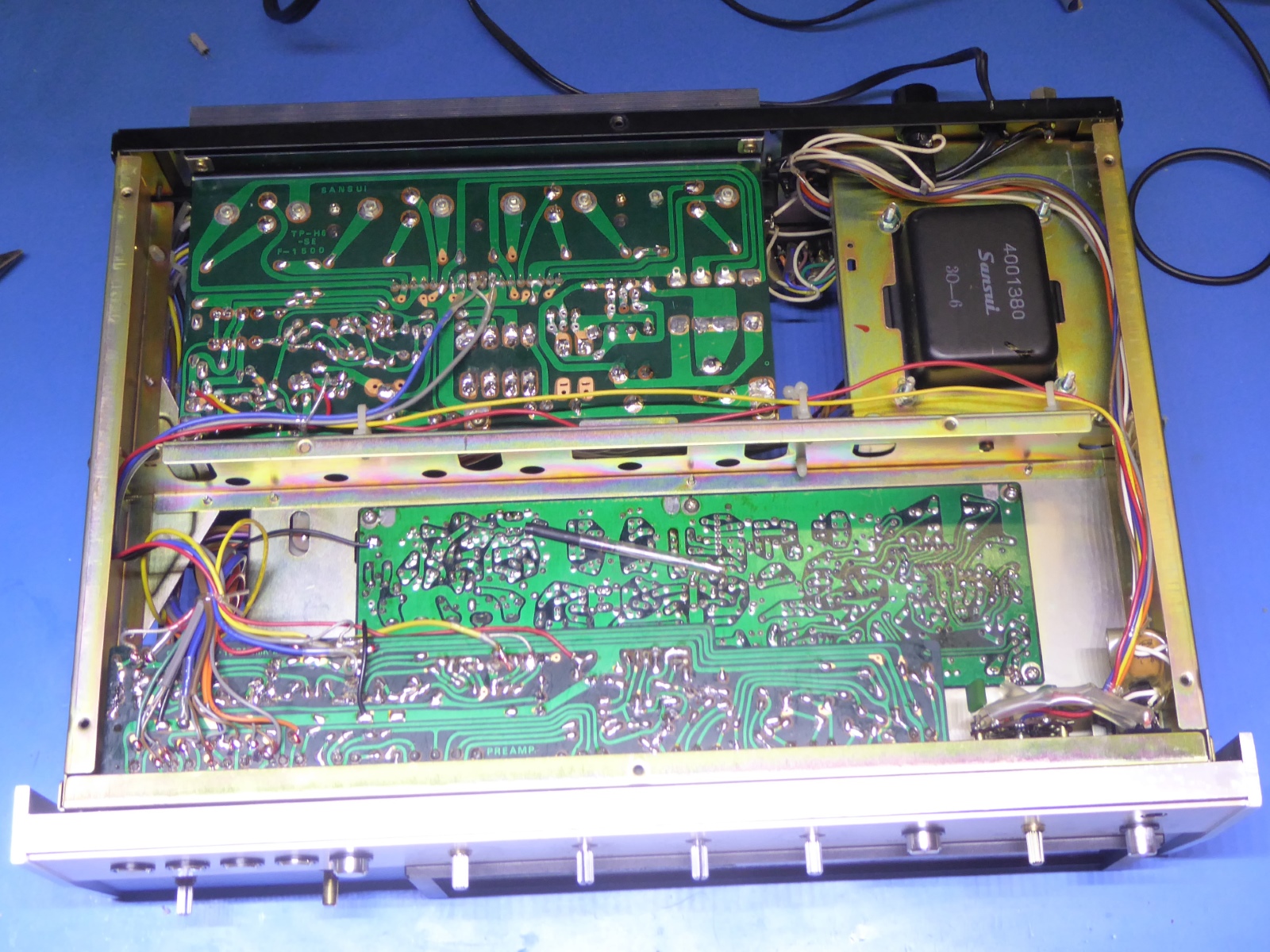
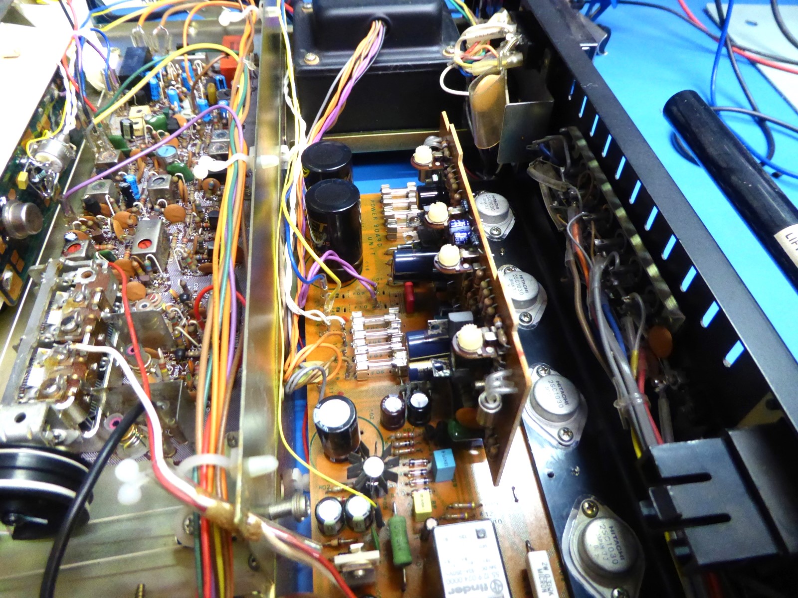
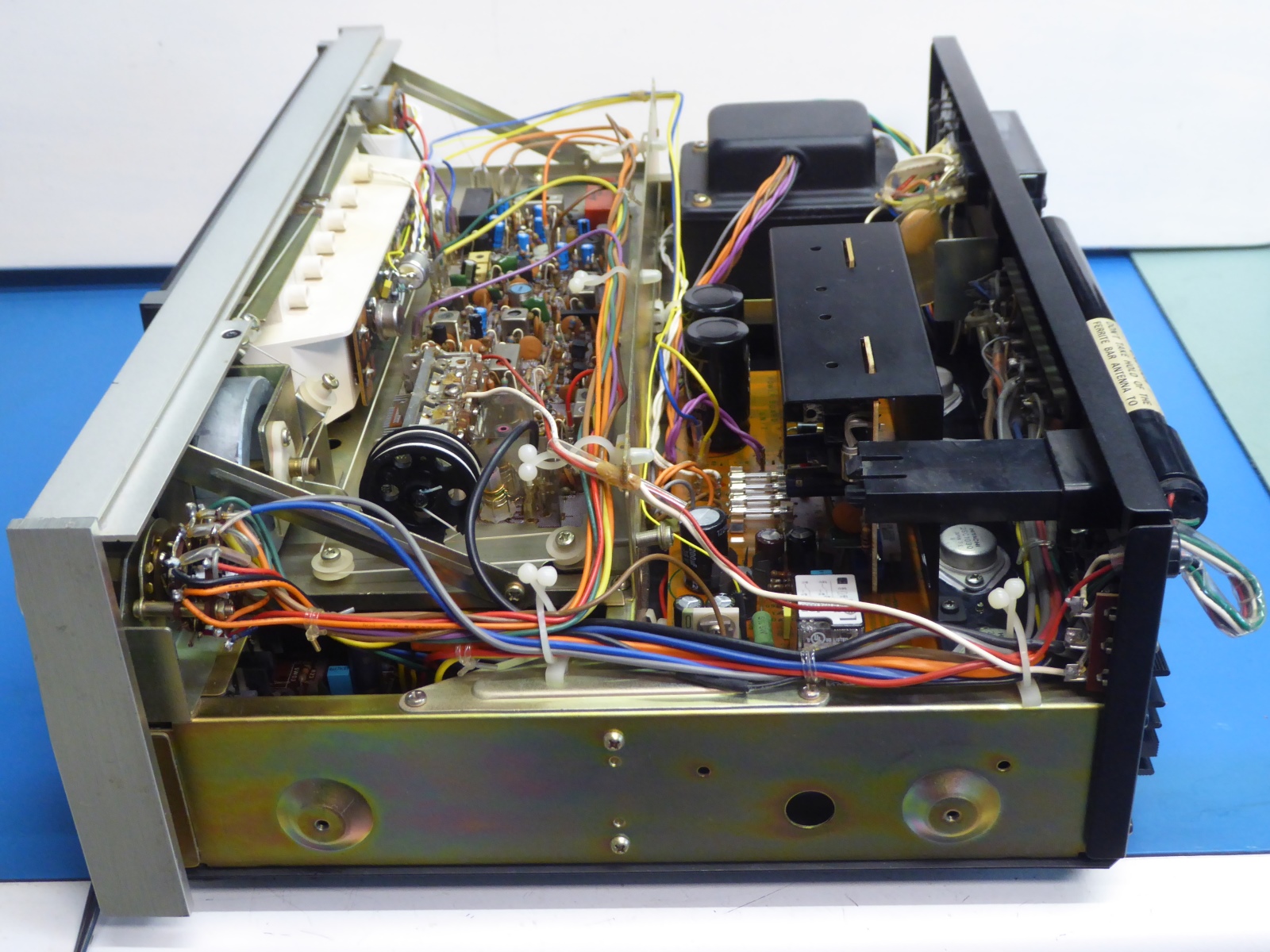
Some pictures of the receiver.














Ga naar Gerards andere pagina's / go to Gerards other pages ---->>> ![]()
