Ga naar Gerards page / go to Gerards other pages ---->>> ![]()

Receiver Sansui Seven refurbishment /recap, 2015.
This Sansui Seven was sold to a Sansui collector, march 2024.
Gemakshalve is deze pagina in het Engels geschreven.
![]() This page is written using English language only.
This page is written using English language only.
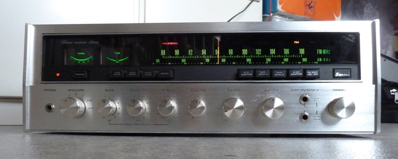
This Sansui Seven was bought in still working condition.
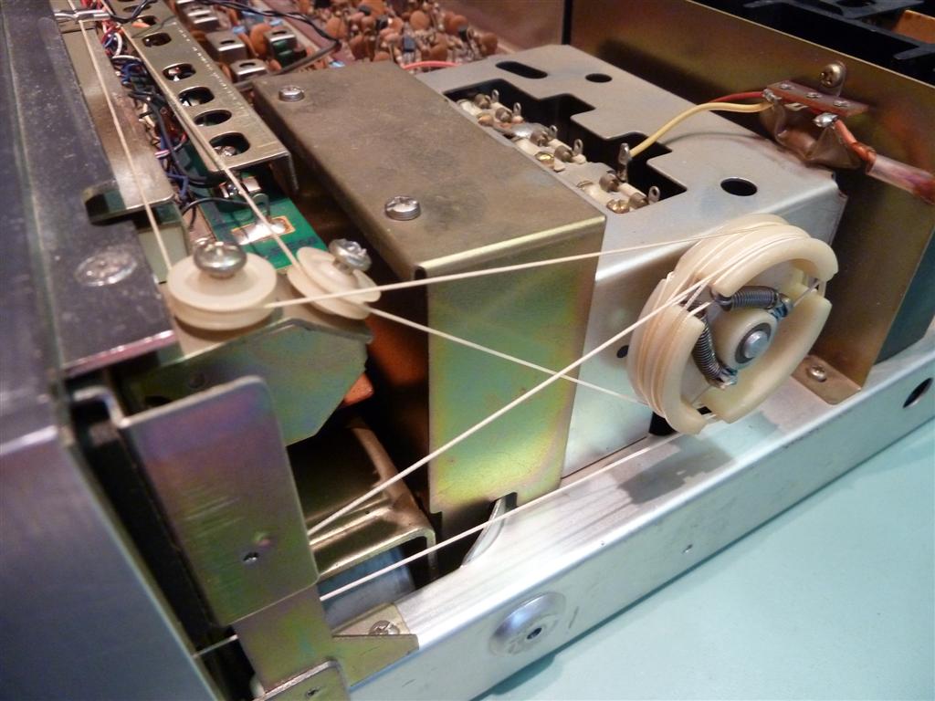
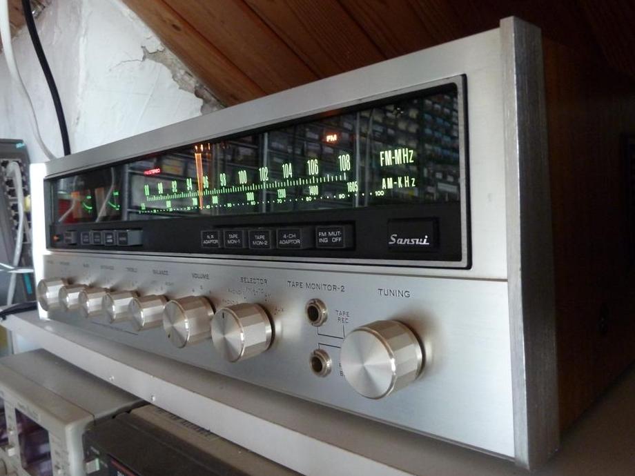
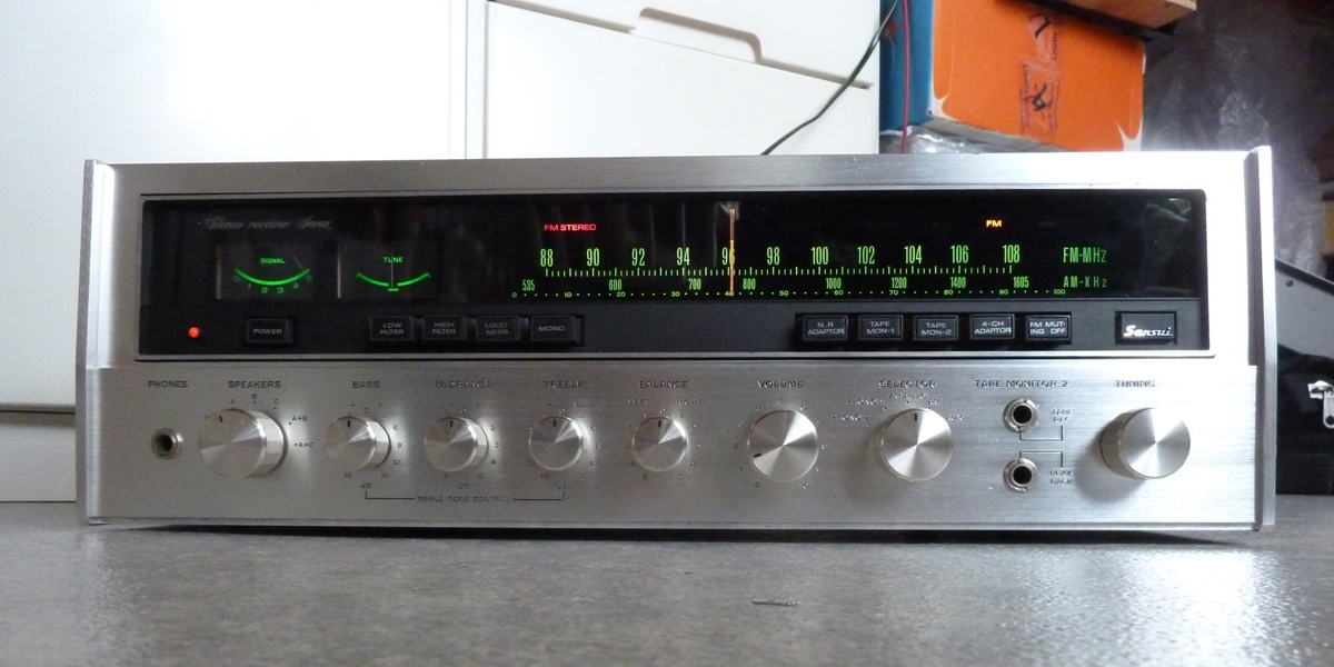
The Sansui Seven is a small heavy 36 watts receiver. The build quality is very sturdy.
Features to be mentioned are a "4-gang tuning capacitor" for FM, 6 ceramic filters (using a lot of these was quite new around 1972) and tone control rotary switches instead of potentiometers.
The manual is available from different sources, for example on Elektrotanya, The schematic is available on Vintageshifi.

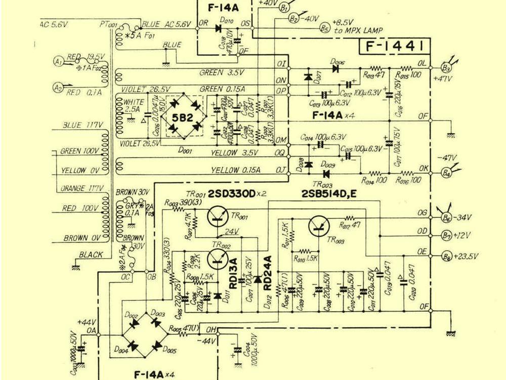
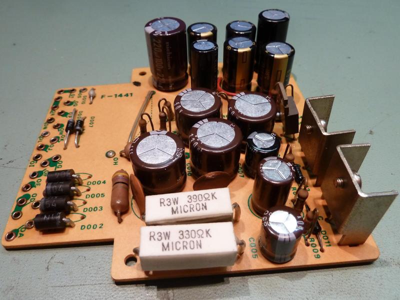
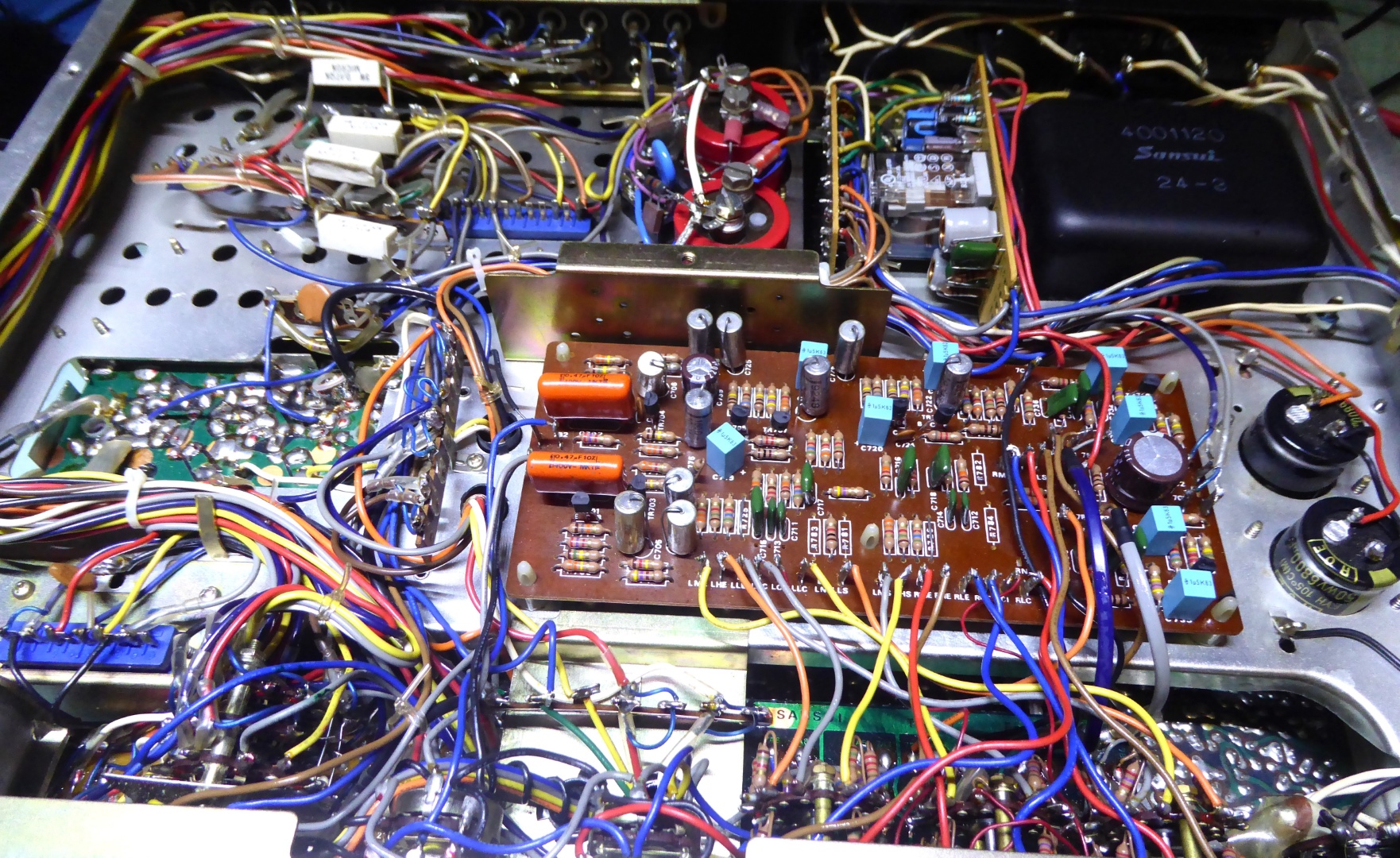
Power supply, card F1441
The power supply supplies several voltages:
B1/B2: + and - 40 volts for the transistor amplifier output stage.
B3/B4: + and - 7 volts, added to the 40 volts outputs, to make + and - 47 volts for the main amp driver stages. Note: this is a voltage doubling arrangement since 3.5 volts transormer windings are used.
B5: +8.5 Volts, for the MPX stereo indicator lamp.
B6: -34 Volts, for the Turntable input amp and the tone amp.
B7: +12 Volts, for the tuner.
B8: +23 Volts, for the stereo decoder electronics.
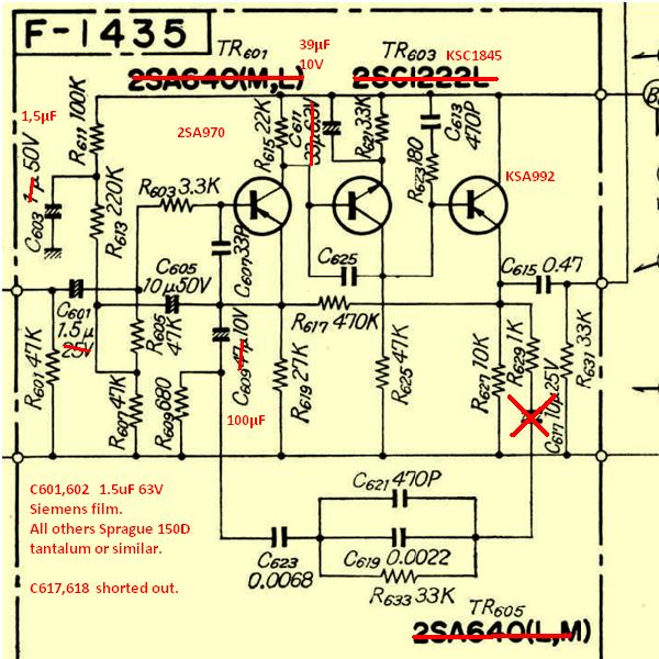
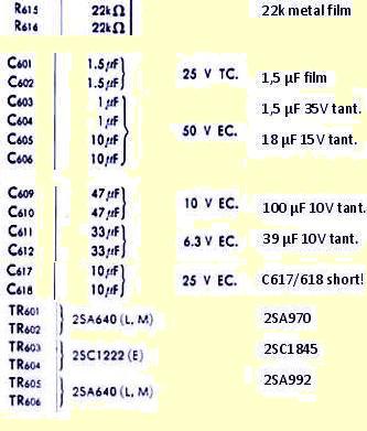
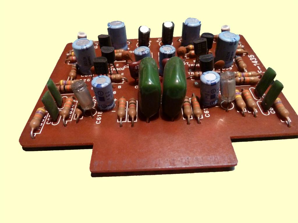
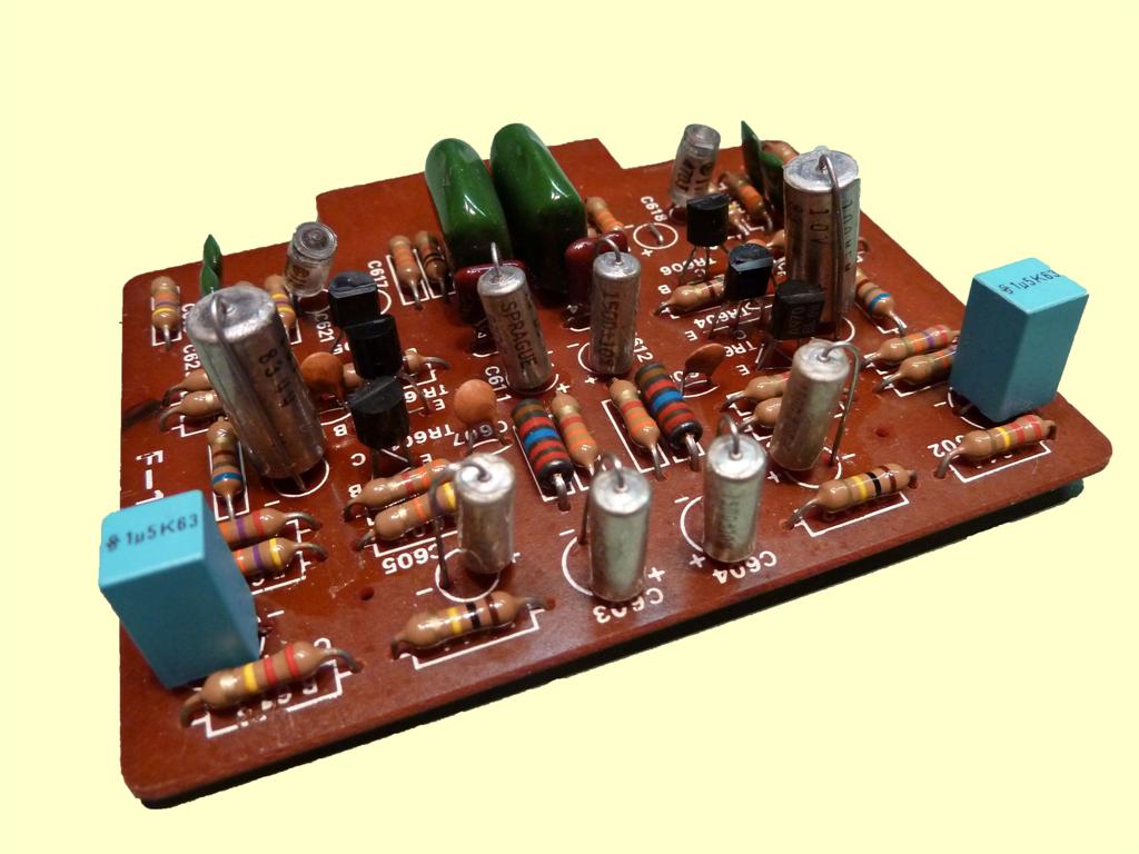
MM turntable equalizer card F1435
This moving magnet preamp did get new transistors, and the aluminium electrolytics were replaced.
One thing to mention is the fact the capacitors C617,C618 do "nothing except for adding to parts count", so they are removed and shorted out, now. This, because C623 and C624 already do the DC voltage blocking.
The old and the present situation
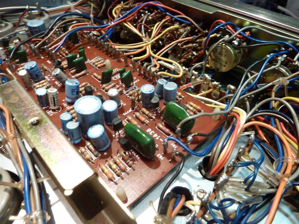
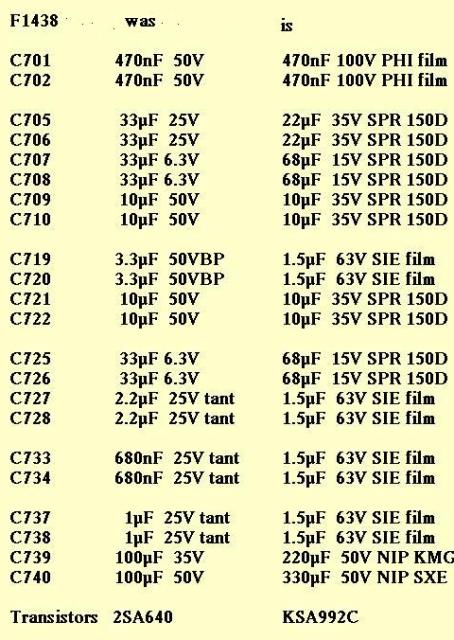
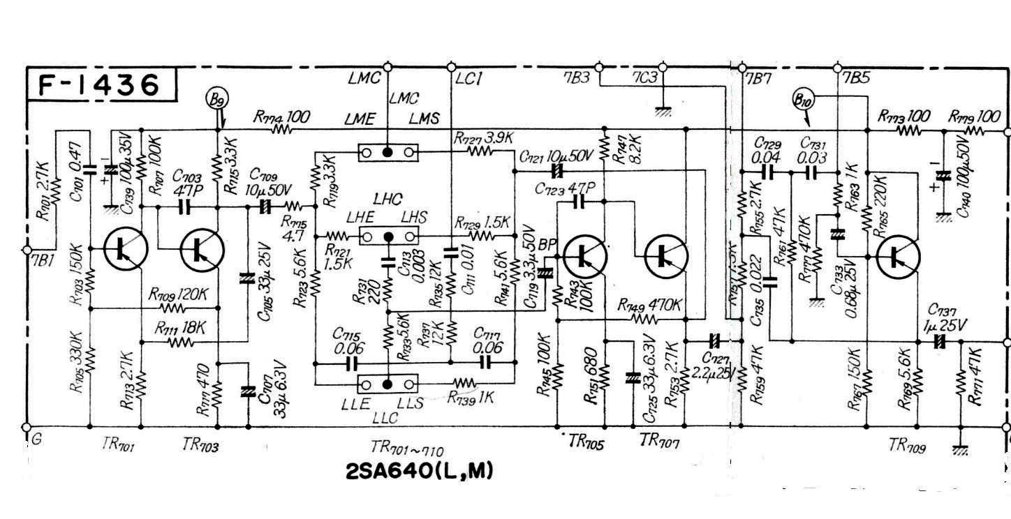
Tone control block F1436
The tone amp leads had to be unsoldered to take out this circuit card. As the wire lugs are deformed on the bottom side and soldered afterwards, they can not just be unsoldered without damage. On the left side of C721 in the middle of the schematic, a 56k resistor pulls the DC voltage to ground, so there is a defined DC voltage of zero volts on the tone control, leaving no chance of C709 or C721 getting a wrong DC voltage.
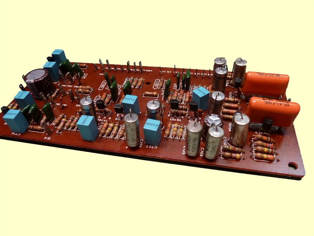
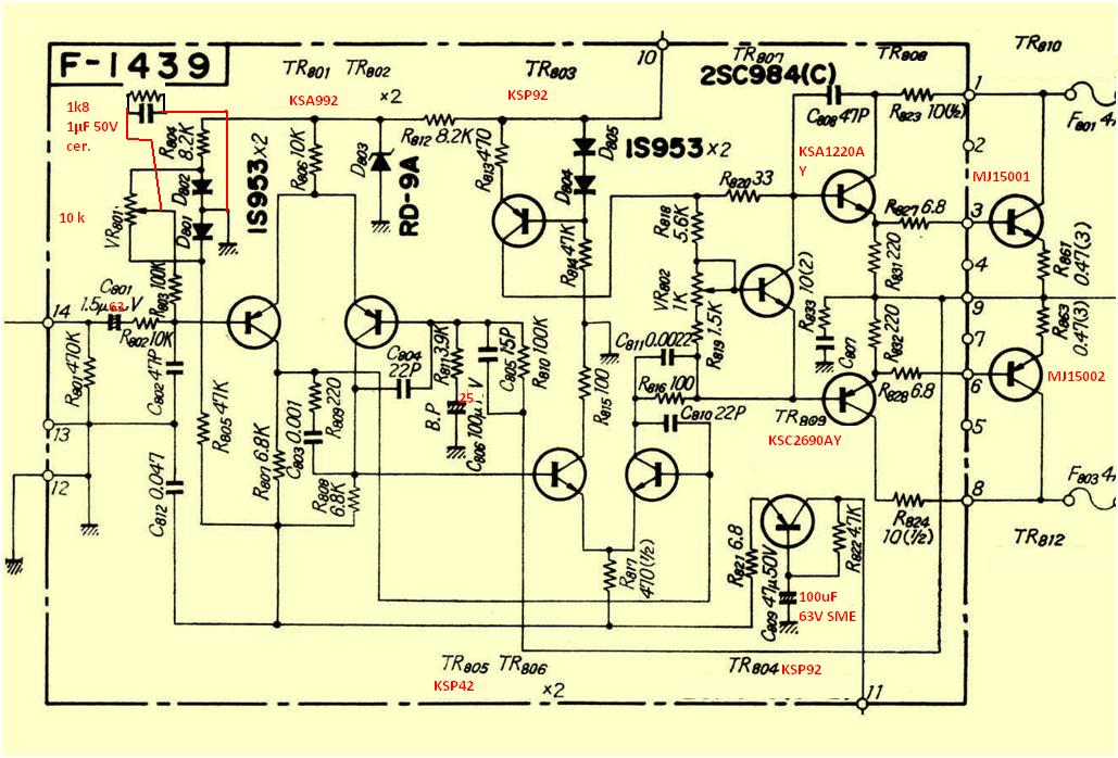
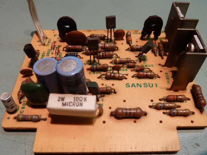
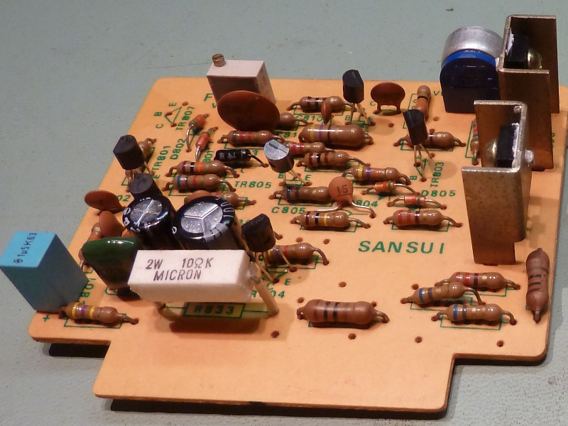
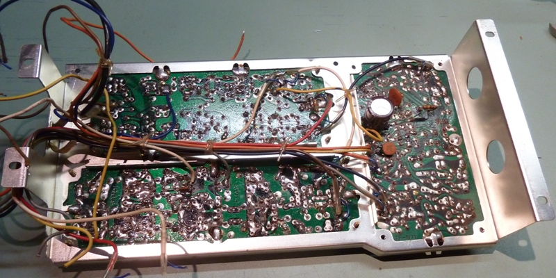
Amplifier driver boards F1439
The mounting of the main amplifier boards appears to have the same setup as is used on the Sansui AU666. for the transistors, only the bias regulating transistors are not replaced, as these are silicon TO-1 style transistor exactly fitting in the mountings at the heatsinks.
The trimming resistors did need to be replaced, as they were deteriorated. The 20 turn ones on the picture appeared not handy enough to reach, so they were replaced by others again.
BTW I did put driver transistor types text the wrong way around....
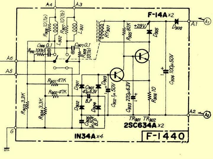
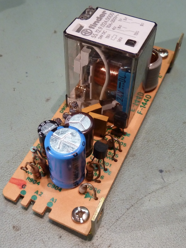
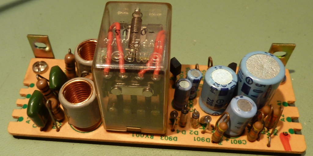
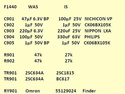
Protector block F1440
The protector card has a new relay, the electrolytic capacitors were replaced, as were the transistors. To ensure enough HFE the relay driver transistor is a darlington type, now. Both 1 µF capacitors were replaced by CK06BX multilayer ceramics. R901 and R902 are changed from 47k to 27k, as the available bipolar cap went from 47µF to 100µF.
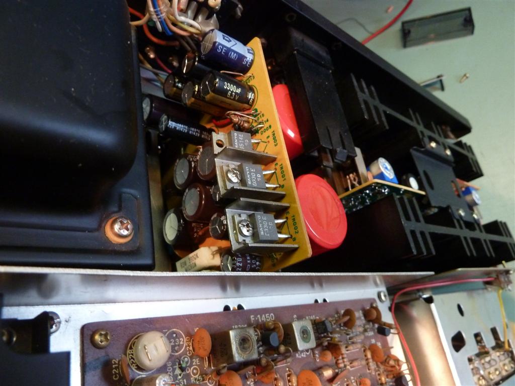
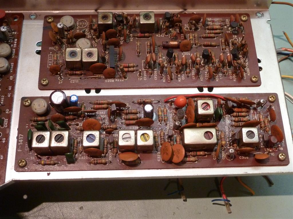
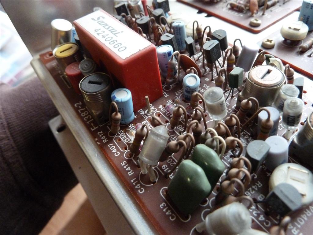
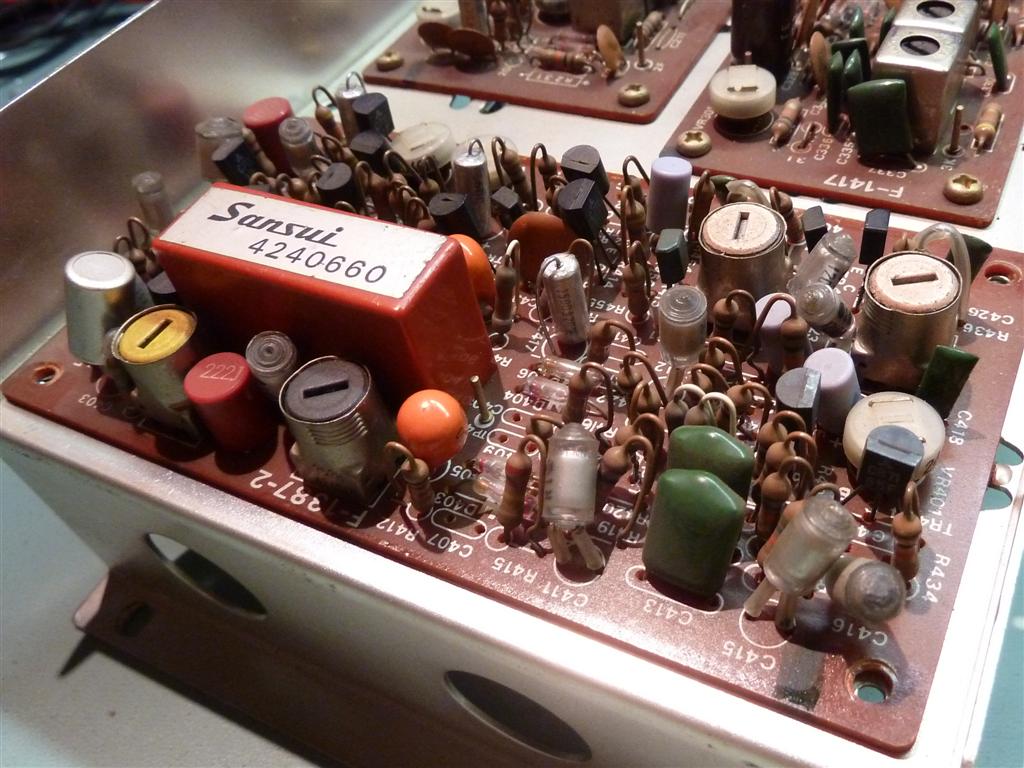
F1417 AM tuner FM tuner R3037U, FM IF F1450, FM decoder/MPX out F1387-2
In general, all Aluminium electrolytic capacitors are replaced and the "solid aluminiums" (light purple colored) are not touched. While the tuner works well, and I lack tuner adjusting experience, I left alignment as is.
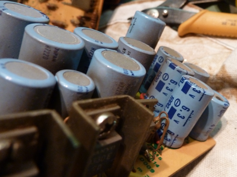
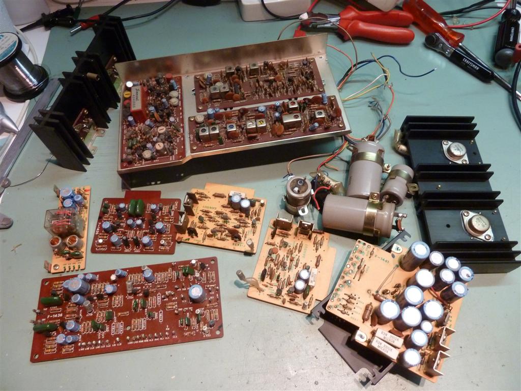
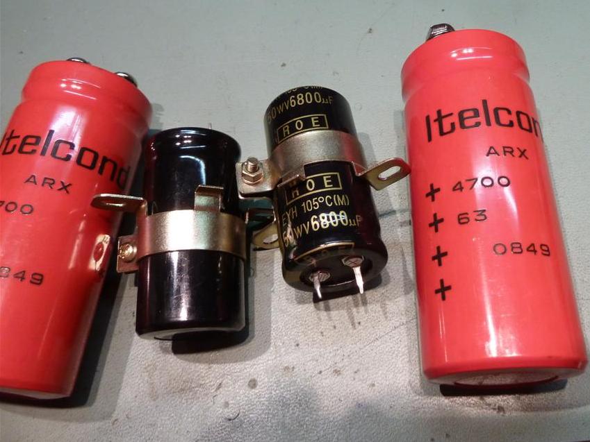
The cards etc taken apart, and the supply main capacitors going in.
In use in the hobby corner now.

Ga naar Gerards page / go to Gerards other pages ---->>> ![]()