Ga naar Gerards page / go to Gerards other pages ---->>> ![]()

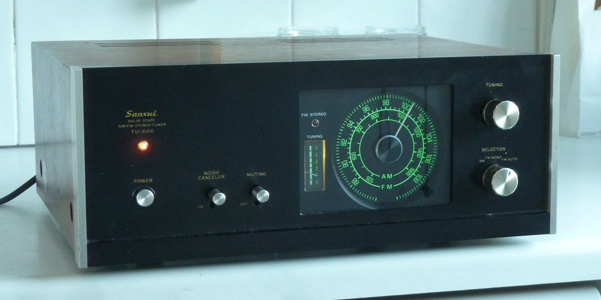
Sansui tu-666 refurbishment /recap 


Gemakshalve is deze pagina in het Engels geschreven.
![]() This page is written using English language only.
This page is written using English language only.

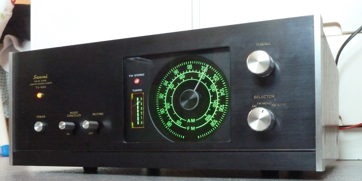
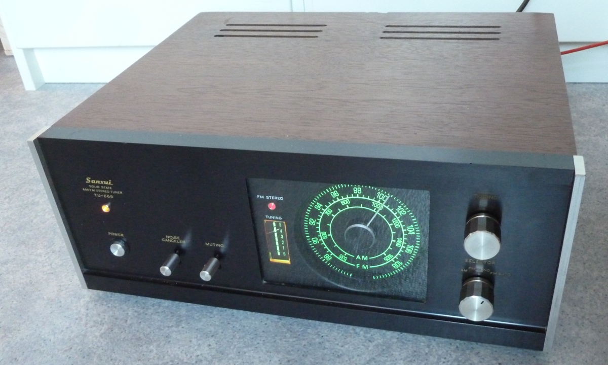
This Sansui TU-666 was bought december 2015 as "defective", it was supposed to loose its frequency setting. The dial string was a bit loose mechanically......
Because of the Sansui hype, these are already much more expensive than comparable tuners having a 3-gang tuning circuit. (one might pay 10 euro's for a comparable Philips...)
This tuner is a nice fit together with the AU-666 amplifier.
The previous owner did some capacitor replacement and cleaning already and he replaced the lamps.
When viewing on a large screen, pictures having old situation are on the left, new situation on the right, in most cases.


The FM tuner
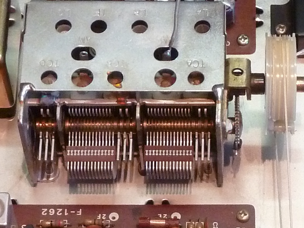
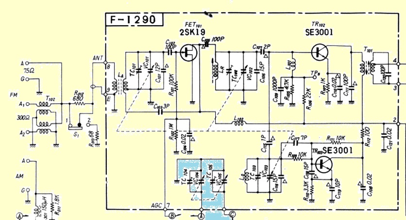
The tuner FM front end is made by ALPS. It is an integrated FM tuner, having additional capacitors for an AM tuner. The shaft of the capacitor assy was cleaned, and it was made sure electrical connections are good. The dial wire needed to be shortened for about one centimeter to work properly again.
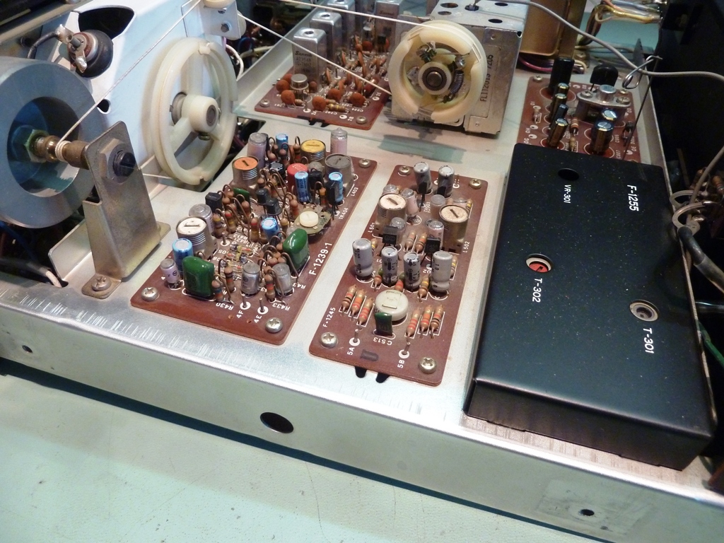

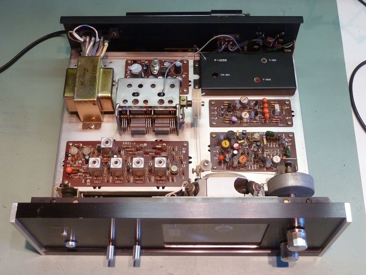



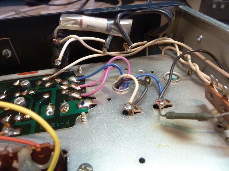
The Bottom Side
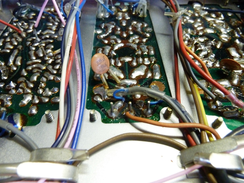
Generally, more than enough solder was used for the boards, and flux residu was not cleaned off. Not on the pictures: The input capacitor on the bottom was changed for a new one. The resistor mounted to the bottom, was damaged by simple touching it, and it was replaced. The power cord was replaced.



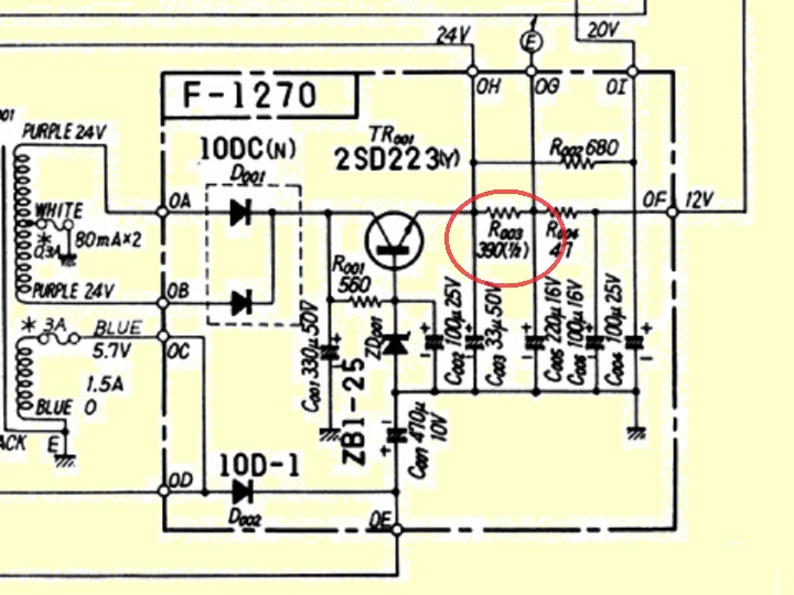
Power supply, card F-1270
24 volts for the MPX circuit card.
20 volts for the audio board.
12 volts for the other boards and FM tuner.
5,7 VAC for the lamps.
7 VDC single wave rectified, for the stereo lamp.
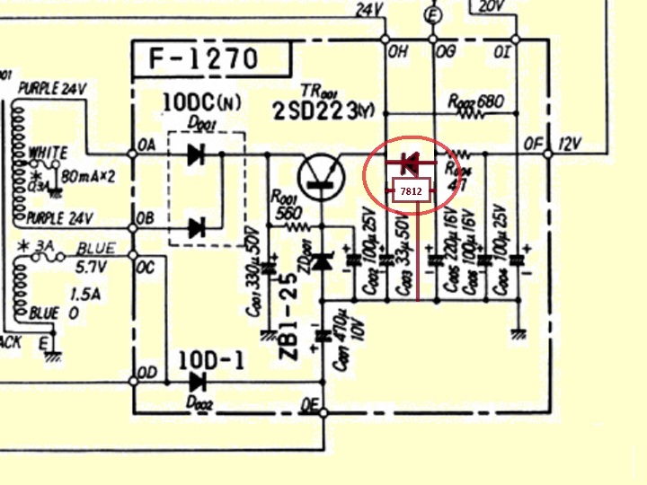
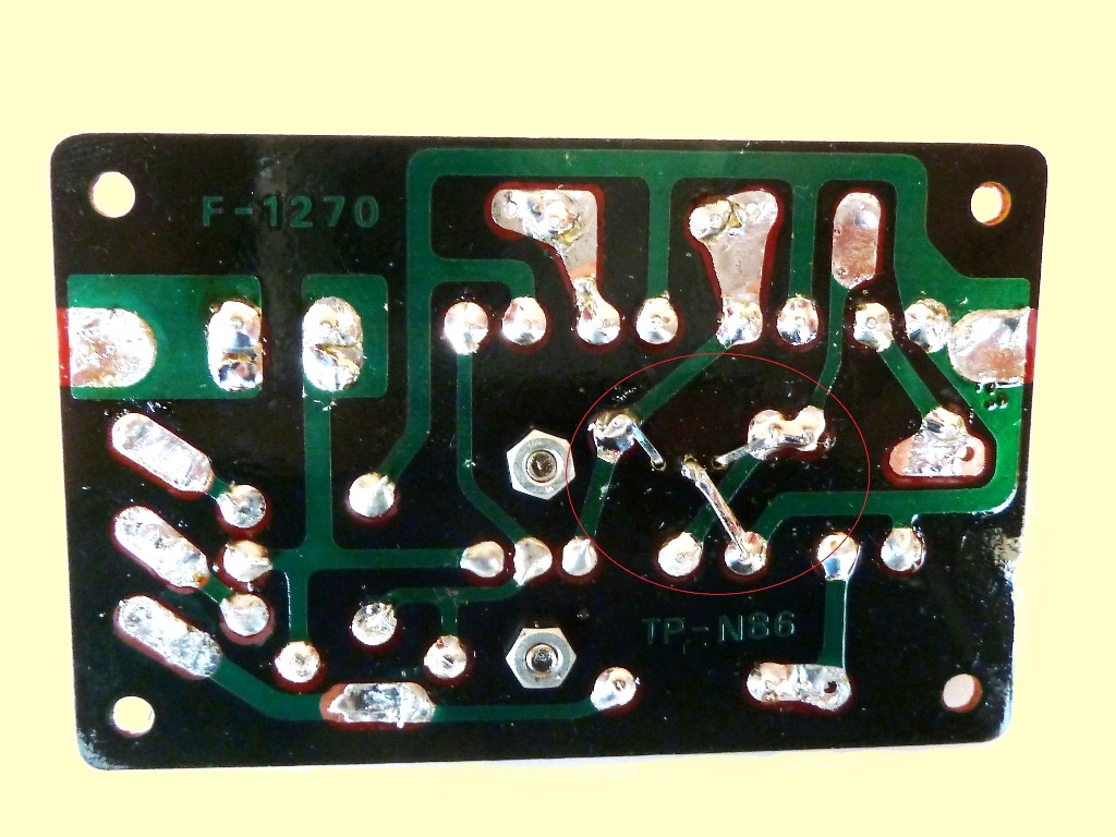
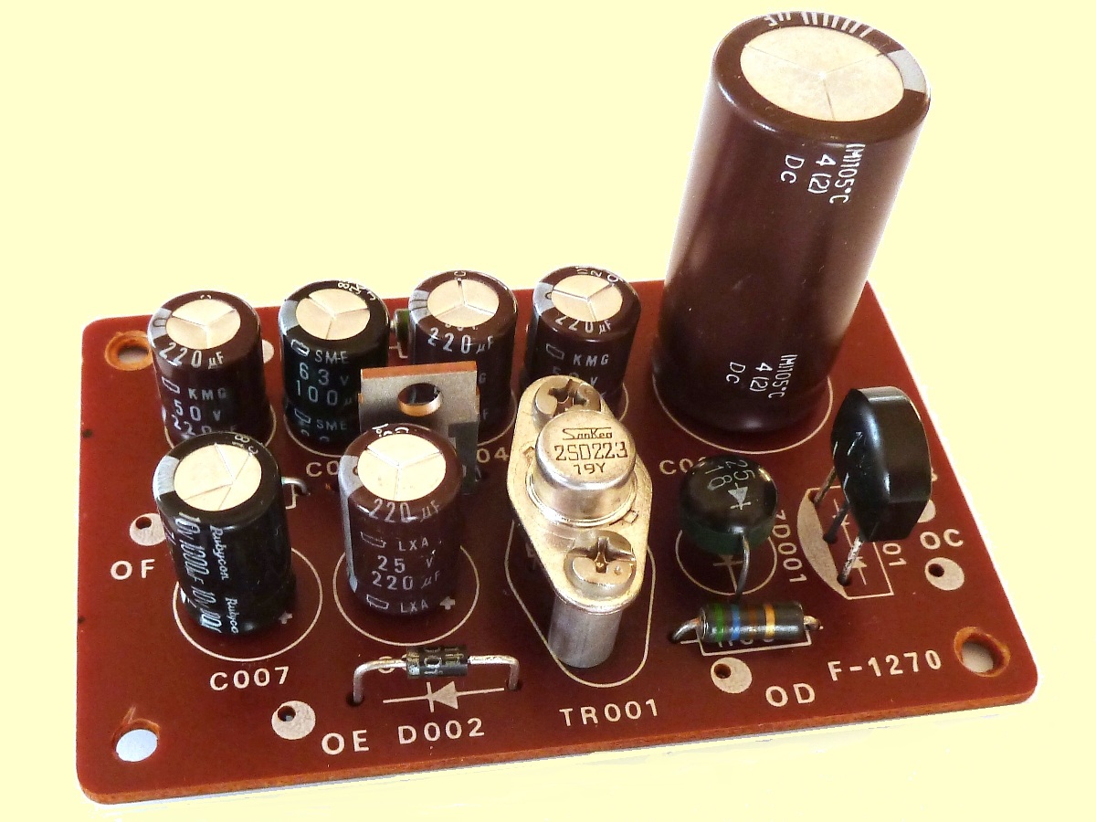
As the 12 Volts power did flutuate a lot when receiving a station or not, a 7812 voltage regulator was put instead of the R003 resistor to create a stabilized power supply.
Holes were drilled for it. A reverse protection diode was mounted instead of the original resistor, while the holes were there, already.
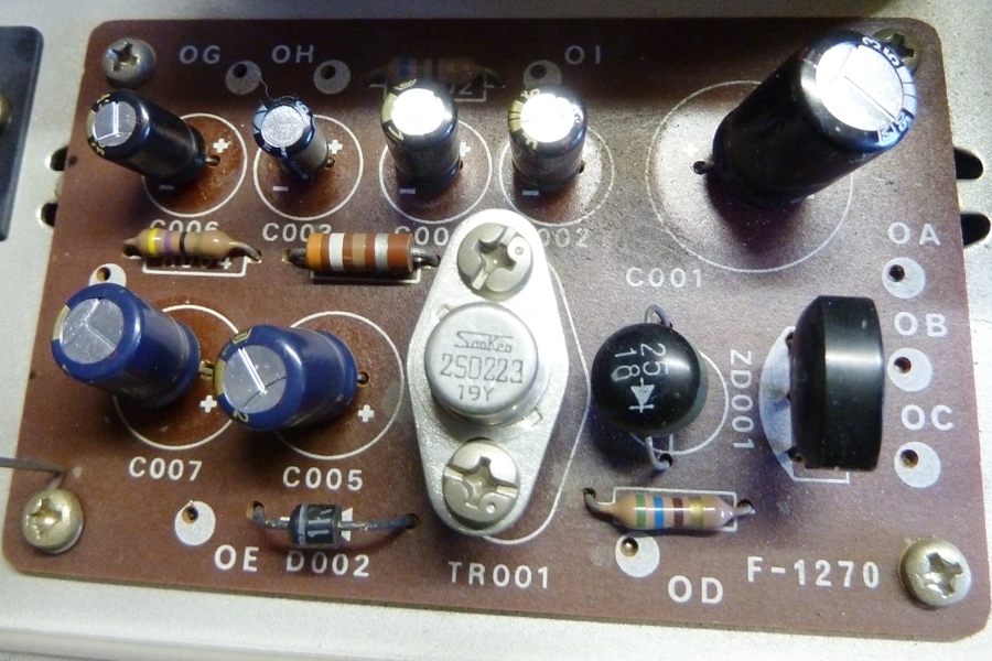
Although the board was already recapped properly by the previous owner of the tuner, all capacitors did get replaced by bigger values, properly matching pcb size.
No matter of need, just preference... The pictures show, it was not a big modification.






AM tuner card F-1255
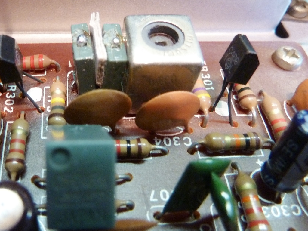
The AM tuner is covered by a metal shield. It appeared to be intermitting, maybe because of touching the board while replacing capacitors. The problem appeared to be the ceramic filter.
It was taken apart and an unsuccessful attempt to fix it using solder was done. It was put back and to maintain mechanical pressure, a piece of paper was put between the two halves. The picture shows these, in front is the loose green filter housing.
All electrolytics were replaced by new aluminium or tantalum electrolytics, and ceramics were used for the 1 microfarad ones.
Checking the tuner during 2020, the AM was not working again. It was decided the green filter to be inspected again, it appeared a dual device and the defective part of it was identified and removed.
AM receiption works again, although what can be expected from AM nowadays, BBC reception is better than the Dutch stations in this part of the country.


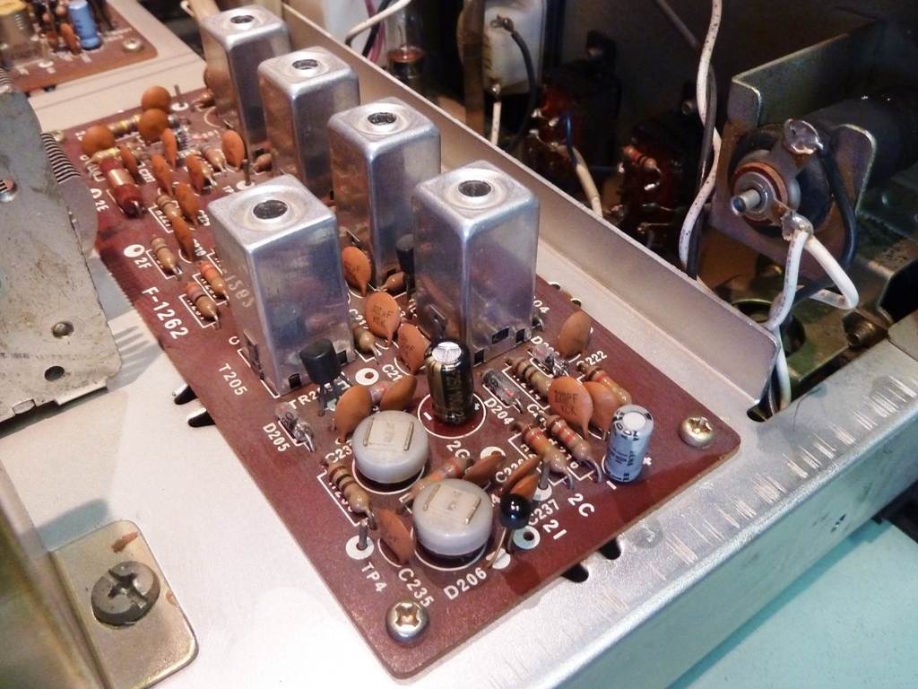
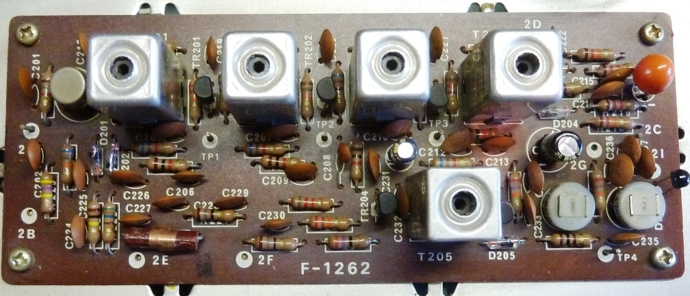
FM IF board board, F-1262
The FM IF board was recapped using components assumed appropriate, and the potentiometers needed to be cleaned (note: a non-residu cleaner called "tuner-spray" was used).



MPX board, F-1239-1
The MPX card was recapped using components assumed appropriate, also this potentiometer needed to be cleaned, also here the taper showed a high resistance.
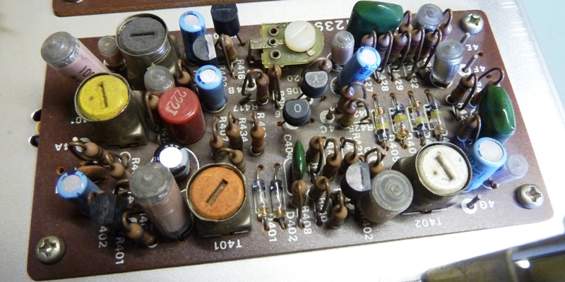

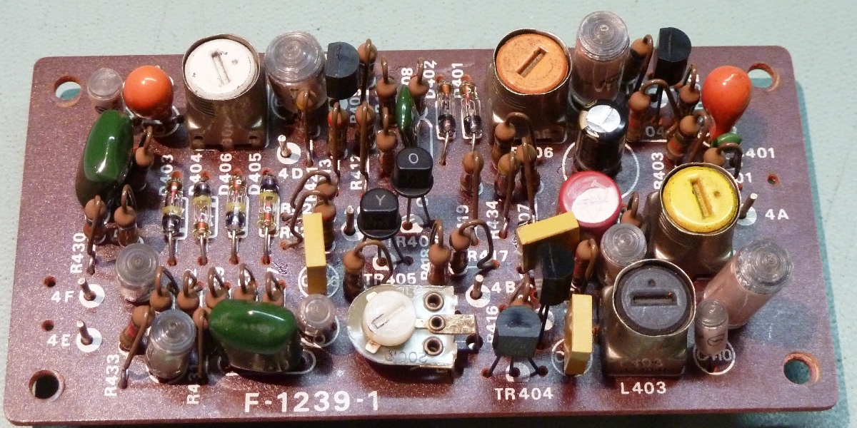


Audio output board F-1245
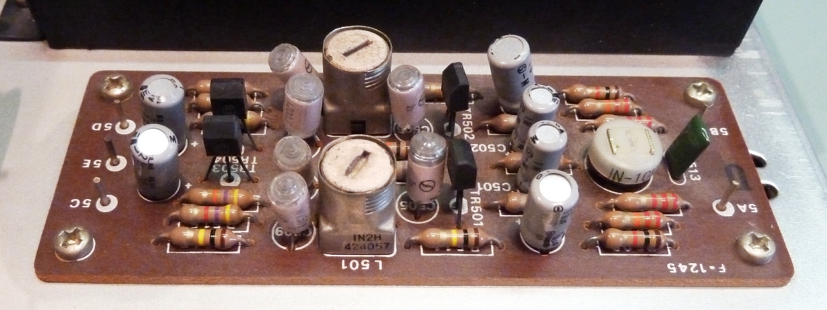
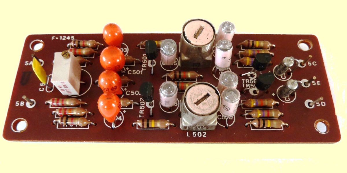
The transistors on this board were replaced by KSC945, selected tantalum caps are being used as coupling capacitors.





Check out this Sansui.us site!


Ga naar Gerards page / go to Gerards other pages ---->>> ![]()
