Ga naar Gerards page / go to Gerards page ---->>> ![]()

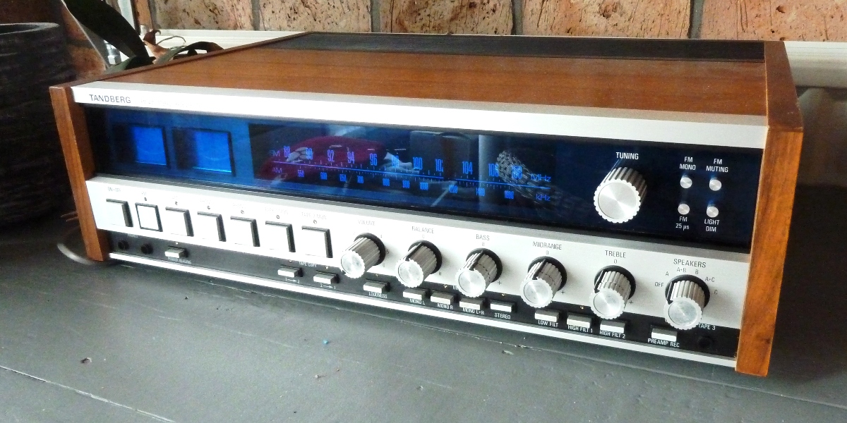
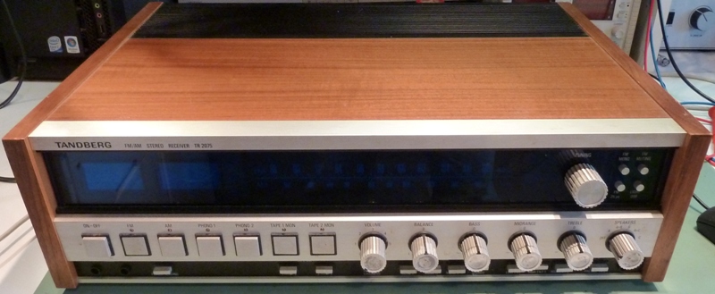
Tandberg tr-2075 refurbishment /recap 2016
Wegens teveel spullen is deze mooie Tandberg toch maar verkocht
Gemakshalve is deze pagina verder in het Engels geschreven.
![]() This page is written using English language only.
This page is written using English language only.
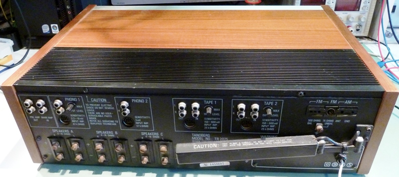
This Tandberg tr-2075 was bought as having an intermitting problem. After powering up, crackling sounds were apparent and the protection relay was taking away the signal many times.
For the "recap", ALL electrolytic capacitors were exchanged for new aluminium or metal case tantalum ones (mostly the Sprague 150D and alike, which ones are found aircraft and military equipment). After tests, only a few of the replaced aluminium capacitors appeared seriously deteriorated.

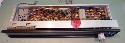
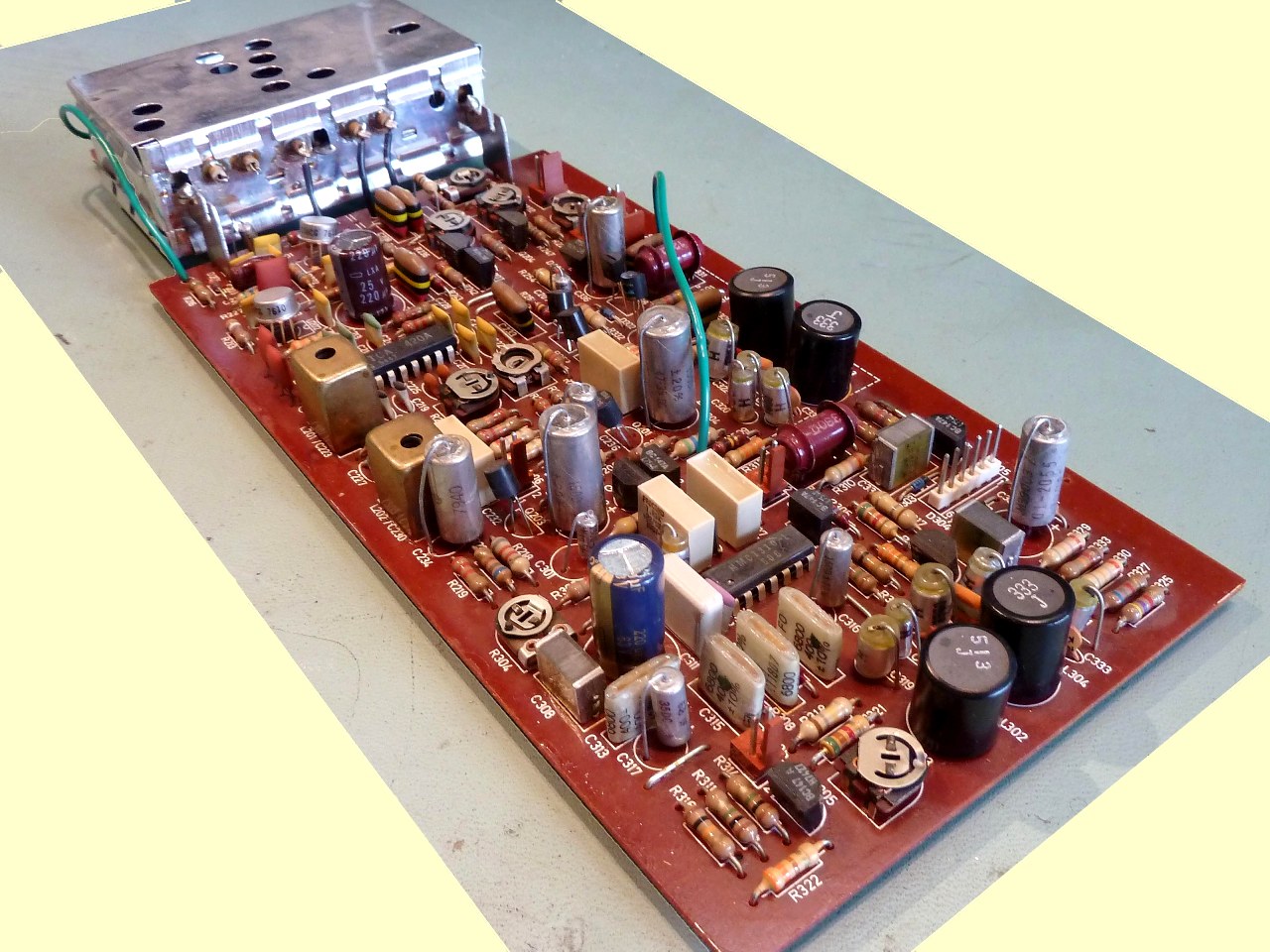
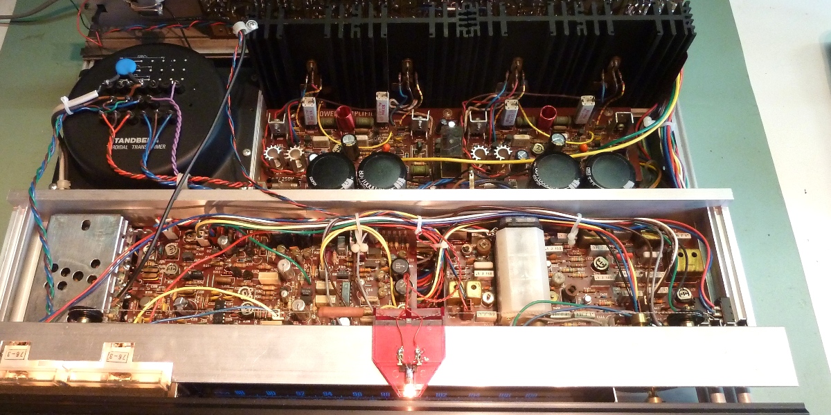
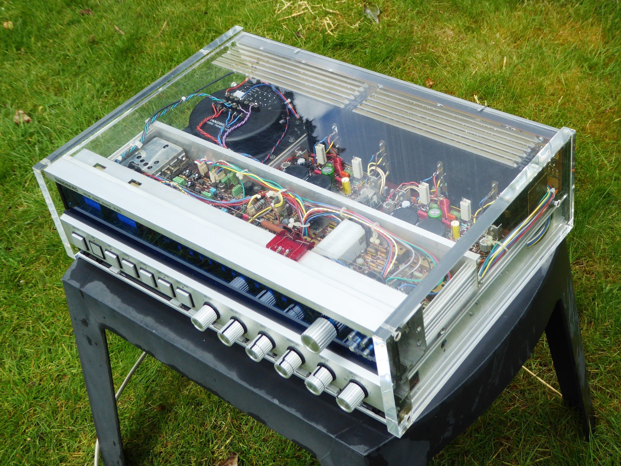
The main amplifier
Each half of the main amplifier has its own rectifier and smoothing capacitors. All electrolytic capacitors were found to be okay, apart from the four big ones all were replaced.
The big ones were replaced later for reliability, as the unit may be sold.
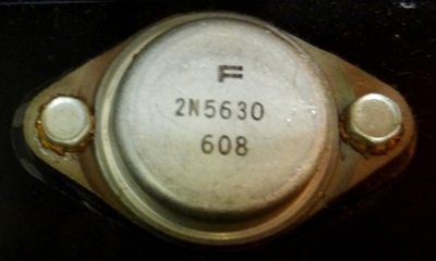
Odd are the M179 and M180 driver transistors in the main amp. There is no data available on those. They are marked with an "F", in such way it does not give any clue about the manufacturer.
Whereas the big output transistors are marked the same, the manufacturer is ASSUMED to be Fairchild.
The differential pairs of input transitors (2SC1583) were replaced by two pairs of matched KSC1845. One of the 2SC1583 had a 1:2 ratio of HFE between the 2 transistors inside the package.
The crackling was not resolved and it seemed not clear what caused it.
As the voltage stages seemed reacting to cold spray, Q909 BF381 was replaced by KSC2330 and the Q907/Q911 BFW44 pair was replaced by selected 2N5416S. This cleared the problem. Afterwards, one removed transistor was considered defective but which one was forgotten.
![]()
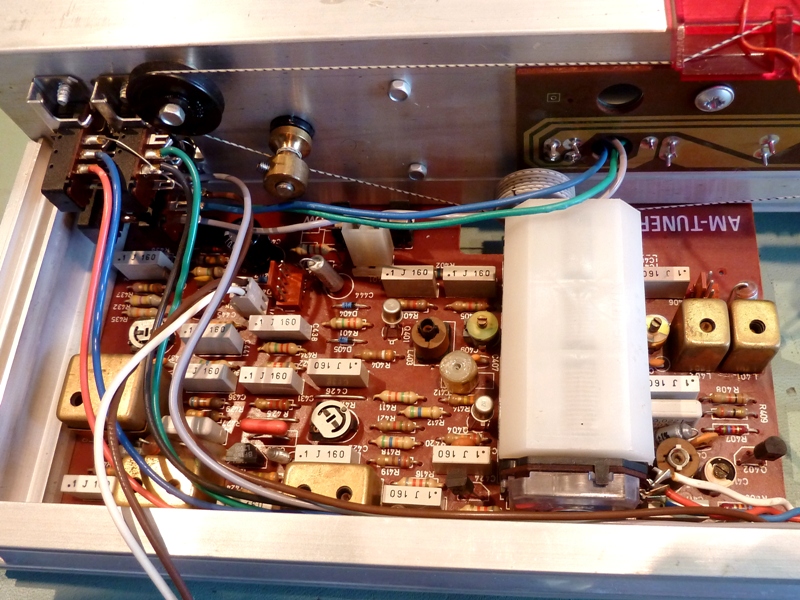
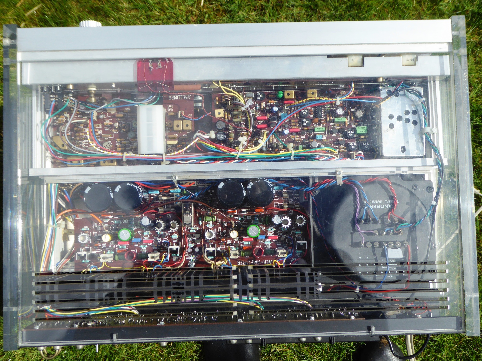
The Tuner assembly
Apart from the antenna wire, which needs desoldering, the whole tuner part can simply be removed from the receiver. This is a very nice feature, which makes interchange or repair very easy.
One very important thing when taking out the tuner, is making sure the metal pieces on the sides of the blue perspex are not falling off/getting lost!
Fortunately, tubular lamps which actually fit could be found to replace broken ones.
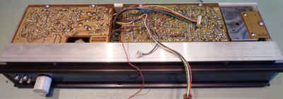
Recapped AM and FM tuner parts. Note: the tuning potentiometer for FM is found on the AM tuner board, attached at the far end of the white AM tuning capacitor.
Four black parts on the FM tuning board look like electrolytic capacitors, but are coils, actually
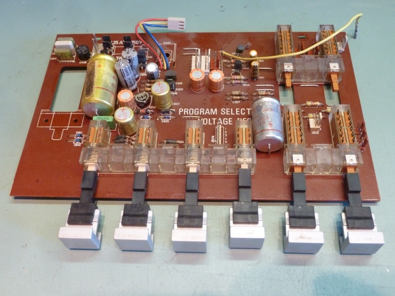
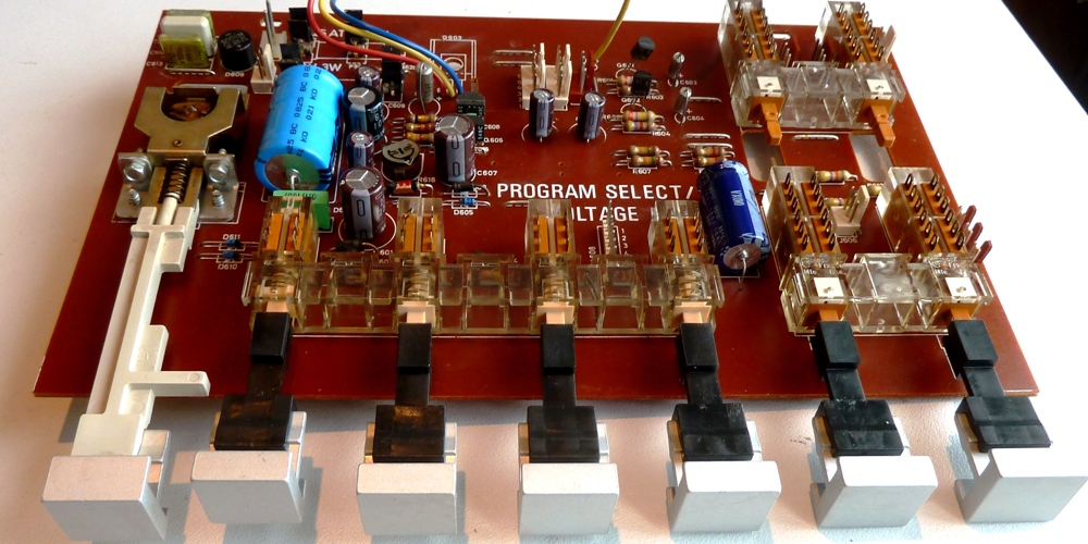
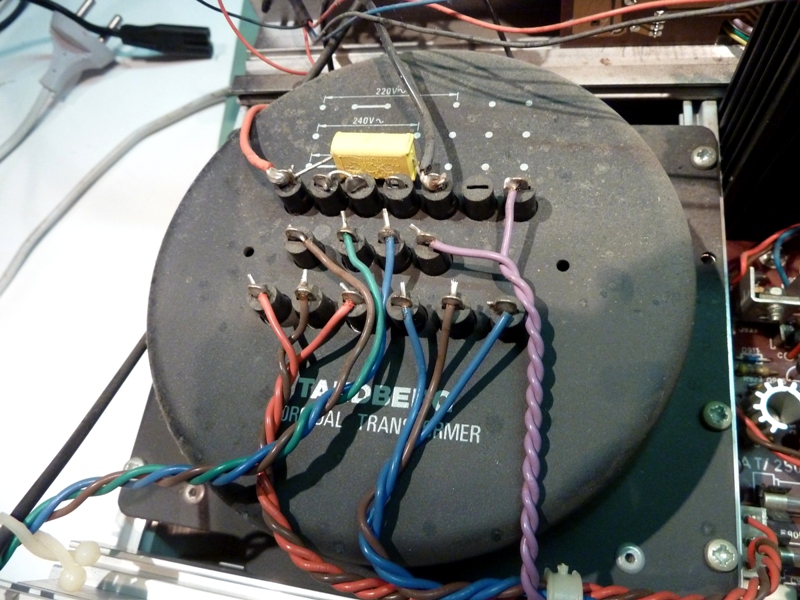
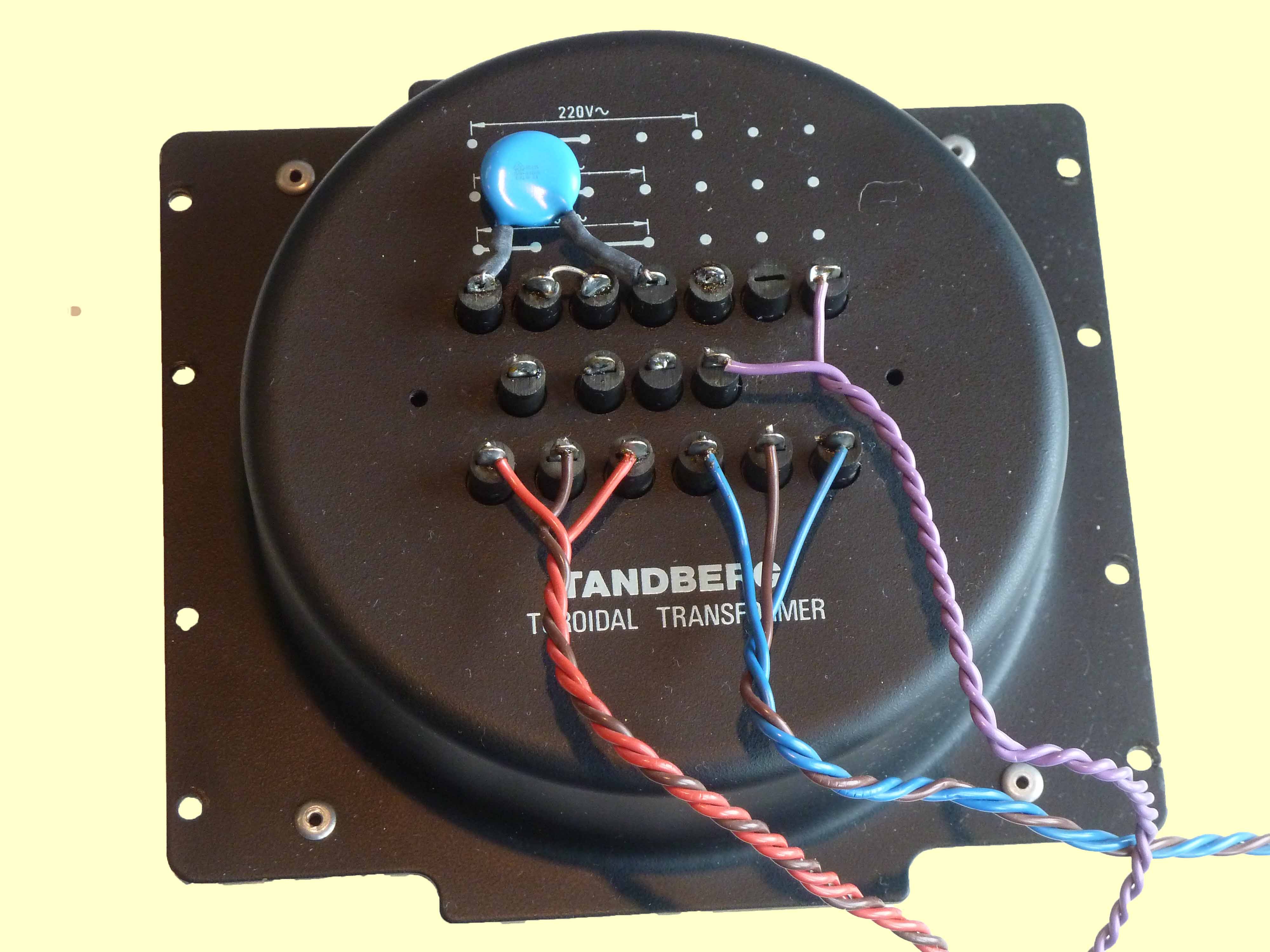
Program Select / Voltage regulator board / Power supply
The transformer has one wire changed, the 240 Volts tap setting is used, instead of the 220V setting from the past.
This will lead to the lamps lasting longer, reliability gets better, safety gets better, this all at the penalty of of a few watts less output power.
10% less lamp voltage doubles lamp life.
Noteworthy is according forum information the big yellow Frako capacitor on the regulator board seems to fail shorted sometimes, causing damage to more parts.
So for this specific type of capacitor, the replacement is not only renewal but also increasing reliability.
Another remark is that apparently Tandberg decided the series pass transistor of the power supply needed mounting on the chassis metal.
The marking on the circuit card suggests a separate heatsink. Maybe it did get hot that way and they decided to move it.
Preamplifier and mode/filter board
The selections are done on the mode/filter board, the preamp board does the tone, balance and volume regulation.
The 10 microfarad capacitors were replaced by tested and known good drop tantalums having extremely low DF.
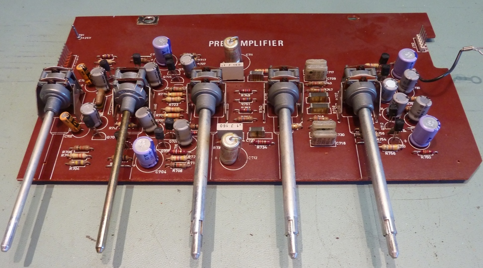
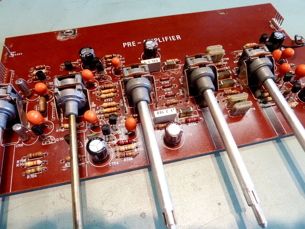
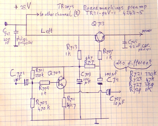
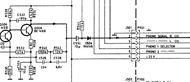
| The input circuit of this preamp differed from any of the schematics to be found on the internet, so there was a need for the schematic.
It basically consists of a capacitance multiplier for the power, and a simple emitter follower for the signal, of course same for each channel. So copy this piece of drawing if working on Tandberg 2075 receivers as you will not find it anywhere else. |
 |
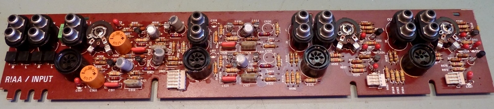
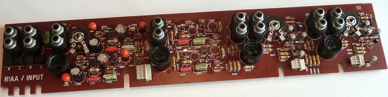
RIAA input board
The RIAA board contained the small red tantalum capacitors which partly showed not able to handle the specified supply voltage, when they were stress tested after taking them out. Of course, they did not get the voltage when still mounted, so they were probably operating correctly. Still, this situation justifies replacing them.
Worth mentioning is the Phono # 2 input was found modified to line level, so it is an "AUX" input now. This is the second TR2075 already found having this modification, which leads to the conclusion Tandbergs choice of having TWO turntable inputs and no "AUX" input was not the smartest one and people want the extra input.
New lamps, partly of the festoon type, hard to find nowadays.
As the unit may be sold, new main power smoothing capacitors were mounted, 10000ÁF 80V brand Nippon Chemicon, together with new bridge rectifiers up to the task of feeding the higher peak currents which can be a result of that.
Go to my Acrylic / Acrylaat / Perspex / Plexiglas version Tr2075 ---->>>>
Ga naar Gerards page / go to Gerards page ---->>> 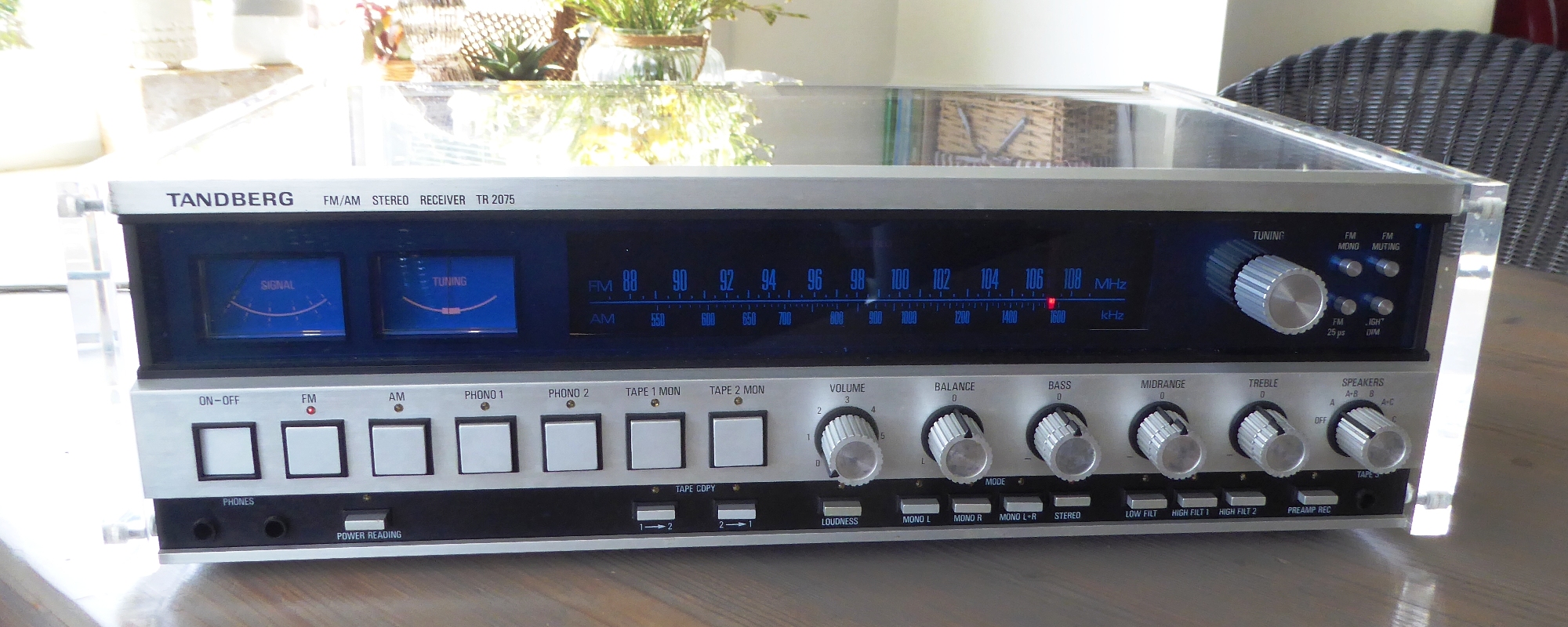
![]()