Ga naar Gerards page / go to Gerards other pages ---->>> ![]()

Luxman L-309V restauratie recap 2014
 See the 2021 one ->>
This amp was sold (2023), having four working Luxman amps remaining was more than enough.
Unfortunately, now march 2026, the amp failed at the new owners place. It was connected as a preamp so NO loudspeakers and NO connection between pre and main amp. Suddenly, there was smoke, the amp was returned and it appears BOTH power amp channels failed (so: all) output transistors and some surrounding resistors. It "just happened" the amp itself was not overheated or so. Now, I need to repair them but more interesting would be finding the actual cause of this vulnerability.... For now, its owner has the main amp output modules from my other L309V so he can continue listening. In the meantime, the repair is in progress and I decided also for these modules drill holes in the heatsink and use a TO-126 type transistor (BD329) for thermal compensation, attached to the heatsink, instead of the vulnerable way Luxman pressed the original transistor using a little clamp. The BF179 VAS transistor will be replaced using a 2N3440 having those now, and the output transistors by new Onsemi MJ15001/MJ15002.
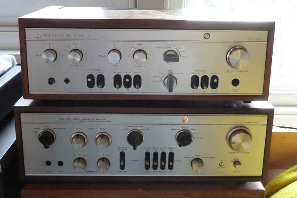
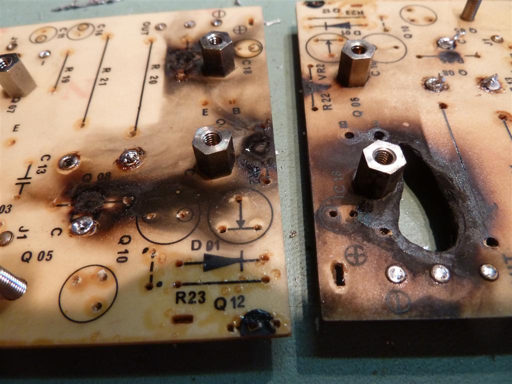
![]() Deze Luxman L-309V had een brandgat in een der eindversterkers, en de andere was ook stuk. Beide defecte eindversterkers zijn opnieuw opgebouwd, en alle aluminium elco's zijn vernieuwd, in 2014.
Deze Luxman L-309V had een brandgat in een der eindversterkers, en de andere was ook stuk. Beide defecte eindversterkers zijn opnieuw opgebouwd, en alle aluminium elco's zijn vernieuwd, in 2014.
![]() This L-309V amplifier rebuilt during 2014 suffered a partly burnt-through amp mainboard and multiple failures of both main amplifiers. Both main amps were rebuilt. A rigid recap and power supply upgrade was done.
This L-309V amplifier rebuilt during 2014 suffered a partly burnt-through amp mainboard and multiple failures of both main amplifiers. Both main amps were rebuilt. A rigid recap and power supply upgrade was done.
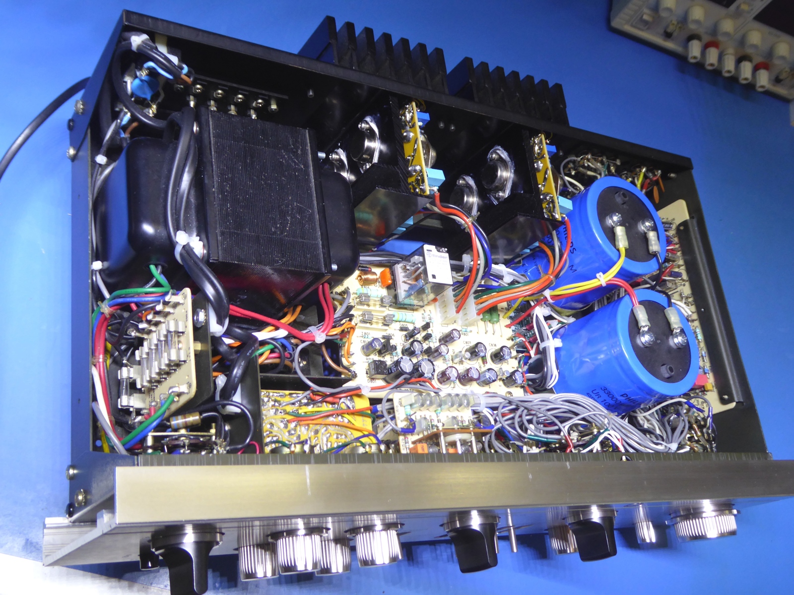
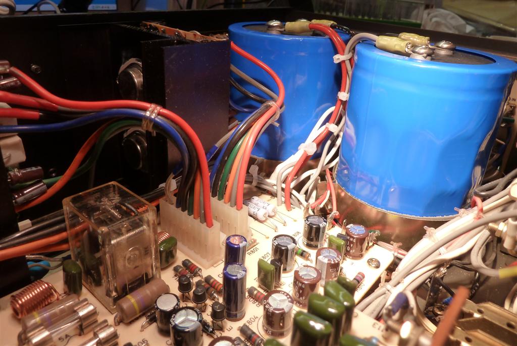
The two main smoothing capacitors are enormous 33000 uF/100 Volts type, now.
They hardly fit into the amp. I had them available, and although oversized I used them, they have a very easy life in this amp.
To be able to put them in, the bleeder resistors have moved to the place where the rectifier diodes resided.
The rectifier diodes are not specified as such, but based on their size I assumed them made for 3 Amps average.
They are not considered suitable to survive the bigger capacitor peak currents at switch-on of the power, and also hardly suitable for an 80 Watts stereo amp like this, already.
They were replaced by a 35 amp rectifier module, which is invisibly mounted below the wiring between the power board and the big capacitors.

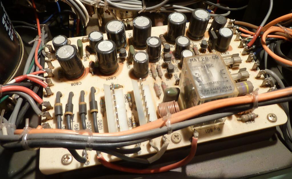
Observe the hole in the pcb on the picture on the right. An earlier repair was done by putting some wire over there, apparently the main amplifier modules were both repaired before.
One of the reasons one sees a lot of failures, is probably only the obvious faulty parts are replaced without addressing possible failure causes, apart from not able to access the modules for measuring while mounted in the amplifier.
There are numerous reports of "crackling sound" and "hick-ups" in old Luxman amplifiers, in general.
The cause may be (and numerous times proven) NOT the failing power stage but the other smaller transistors causing the power stage to fail.
On internet forums, the two little input transistors part numbers are on the "replace whenever you see them" list, as they are supposed to deteriorate.
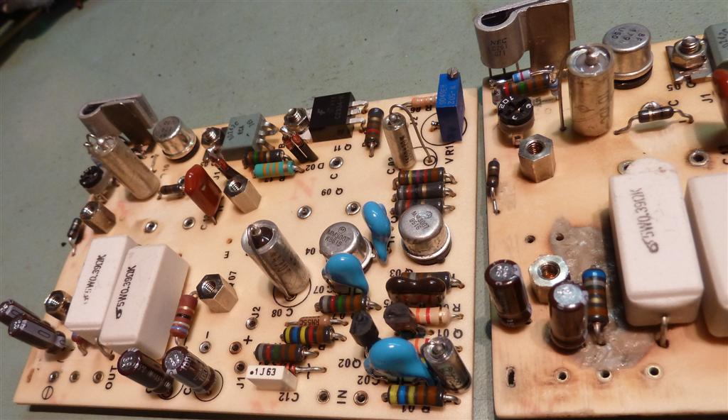
Having a suitable power supply and a test rig with connector I made up, makes it possible to test each module on the bench.
As proven by the previous repair, it is of no use to repair it again as apparently was done, so I swept off all parts and rebuilt the modules.
On the left picture top right, the Bleeder resistors are visible. There was no room for them on the capacitors, they would not fit in the enclosure, anymore..
Just to the right of those bleeder resistors, the big rectifier is mounted on the chassis.
The power supply board, also containing the safety relay circuit, was totally taken apart too, so all the browned glue aroung the old capacitors could be removed, it looks neat again.
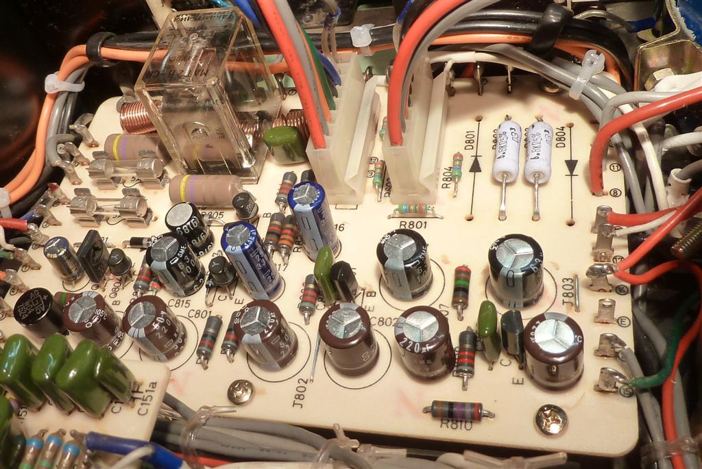
![]() Het gat in de print is gevuld met epoxy, zodat hij netjes bestukt kan worden zonder zwevende draden, tenslotte is het geen oude buizenversterker, waar dat gebruikelijk was. De nieuwe weerstanden zijn meest metaalfilmtypen. Sommige elco's zijn "tantaal" typen, de dure met metalen behuizing, welke je in militaire en avionica toepassingen ziet. De bruine zijn Nippon Chemicon 105 graden typen, theoretisch langere levensduur dan de originele dus.
Het gat in de print is gevuld met epoxy, zodat hij netjes bestukt kan worden zonder zwevende draden, tenslotte is het geen oude buizenversterker, waar dat gebruikelijk was. De nieuwe weerstanden zijn meest metaalfilmtypen. Sommige elco's zijn "tantaal" typen, de dure met metalen behuizing, welke je in militaire en avionica toepassingen ziet. De bruine zijn Nippon Chemicon 105 graden typen, theoretisch langere levensduur dan de originele dus.
![]() The amplifier module pcb hole is epoxy-filled now, I want no hanging wiring like in a tube amp, and it simply looks better.
The amplifier module pcb hole is epoxy-filled now, I want no hanging wiring like in a tube amp, and it simply looks better.
Mostly metal film resistors are used, some metal-case Tantalum capacitors too.
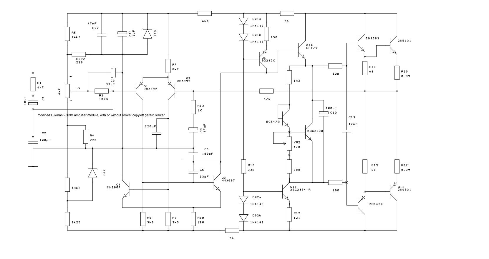
![]() Het schema van de gemodificeerde Luxman L309V eindversterker module, eventuele foutjes voorbehouden. De modificatie betreft de circuits voor nulinstelling en ruststroominstelling, lijkt nu meer op dat van de L85V.
Het schema van de gemodificeerde Luxman L309V eindversterker module, eventuele foutjes voorbehouden. De modificatie betreft de circuits voor nulinstelling en ruststroominstelling, lijkt nu meer op dat van de L85V.
Het originele schema is bijna identiek aan dat van het type L-85V. Helaas is het manual van de L309V nergens op het internet te vinden.
![]() Apart from possible errors, this schematic is as the main amplifiers presently are. Whereas offset and bias circuits have changed, it differs a bit from the real schematic of the Luxman L-309V
Apart from possible errors, this schematic is as the main amplifiers presently are. Whereas offset and bias circuits have changed, it differs a bit from the real schematic of the Luxman L-309V
The L-309V main amplifier schematic is quite different from the "normal" L-309, but it is some 98% the same as the L-85V one.
The L-85V schematics can be found on the internet, but the one of the L-309V seems to be not there. It is good enough to use as a repair guide.
With minor differences, the L-309V contains all the electronics found in the L-85V although placed on different circuit card layouts, including having the very same transformer.
Interior of the amplifier, after the work was done.
It took a few weeks, since all boards were taken loose to be able to replace the aluminium electrolytic capacitors.
.jpg)
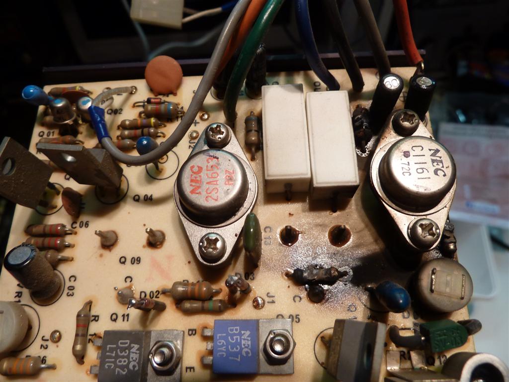
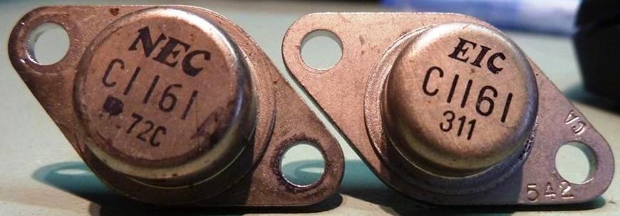
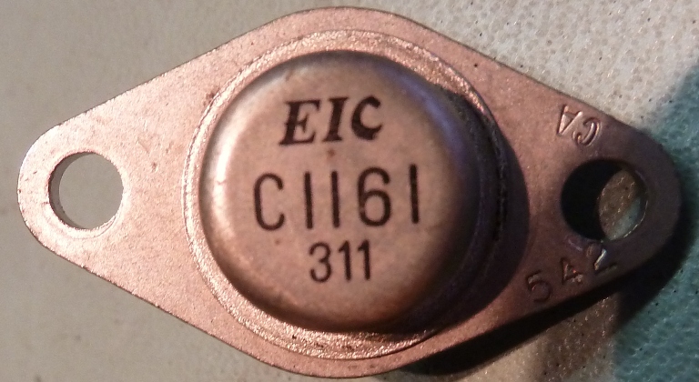
This "EIC" transitor below may be an "aftermarket brand" type. The brand was googled, it seemed to exist, but there is not enough info found to conclude anything.
It was found in one of the main amplifier modules. As the transistor looked old already, this apparently was from a repair long ago.
Although a Taiwan ETC brand exists, it is believed they were only making diodes during those days, if already in business. In the meantime, I found EIC transistors in another Luxman (308) .
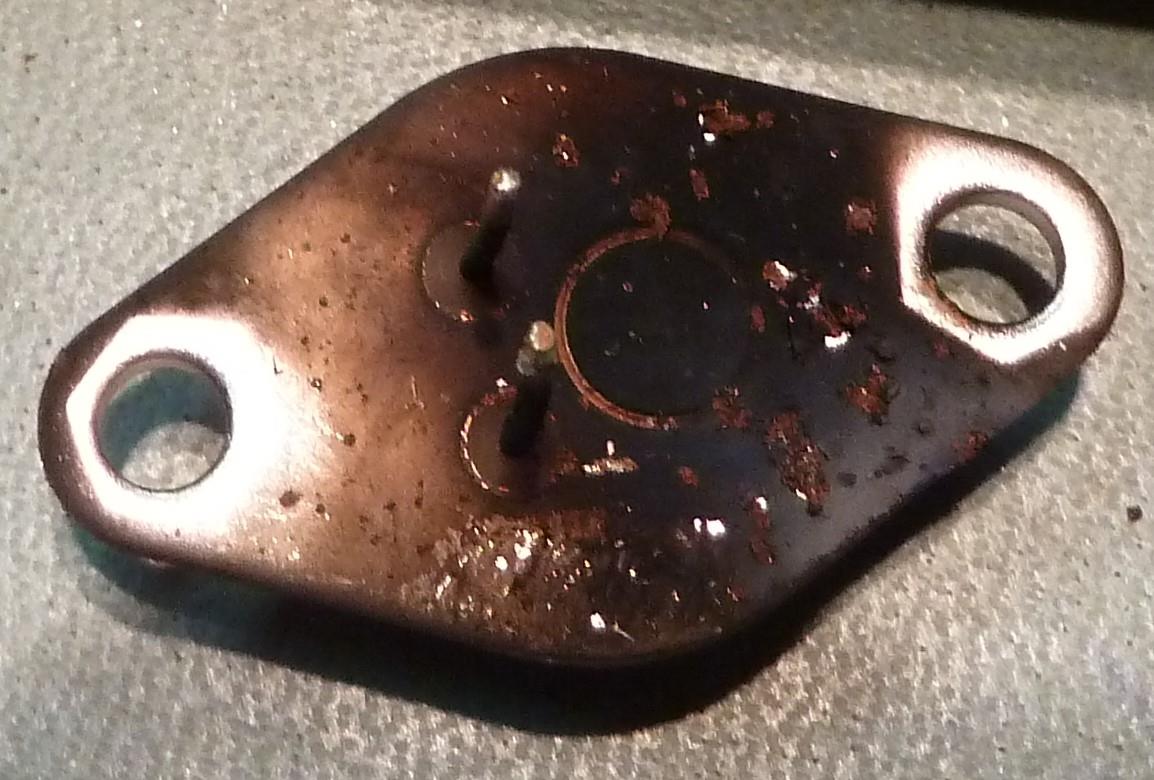
The picture on the right makes one wonder, how hot one of the transistors went, or was it burnt by a resistor?....
SQ507X en L-309V
See my other L-309V refurbished during 2021
Ga naar Gerards page / go to Gerards other pages ---->>> ![]()